|
Os motores de busca de Datasheet de Componentes eletrônicos |
|
|
Os motores de busca de Datasheet de Componentes eletrônicos |
|
PC87307 Folha de dados(PDF) 16 Page - National Semiconductor (TI) |
|
|
|
|||||||||||||||||||||||||||||
PC87307 Folha de dados(HTML) 16 Page - National Semiconductor (TI) |
|
|
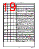
16 / 218 page  16 Signal/Pin Connection and Description www.national.com CFG3-0 148, 146, 144, 138 Configuration Input Group 5 Configuration Strap Pins 3-0 – These pins determine the default configuration upon power up. These pins are pulled down by internal 30 K Ω resistors. External 10 KΩ pull-up resistors to V DD should be employed. CFG3 is multiplexed with SOUT2. CFG2 is multiplexed with RTS2. CFG1 is multiplexed with DTR2 and BOUT2. CFG0 is multiplexed with SOUT1. See Table 2-2 on page 25 and Section 2.1 on page 24 for more information. CS0 68 General Purpose Output Group 21 Programmable Chip Select – CS0, CS1 and CS2 are programmable chip select and/or latch enable and/or output enable signals that have many uses, for example, as game ports or for I/O port expansion. The decoded address and the assertion conditions are configured via the chip configuration registers. See Section 2.3 on page 26. CS0 is an open-drain pin that is in TRI-STATE unless VDD is applied. CS2 is multiplexed with XD1, CS1 is multiplexed with XD0, and CS0 is multiplexed with CSOUT-NSC-Test. CS2,1 72, 71 General Purpose I/O Group 9 CSOUT- NSC-Test 68 NSC use Output Group 21 Chip Select Read Output, NSC-Test – National Semiconductor test output. This is an open-drain output signal. This signal is multiplexed with CS0. CTS2,1 141, 131 UART1, UART2 Input Group 1 UART1 and UART2 Clear to Send – When low, these signals indicate that the modem or other data transfer device is ready to exchange data. The CTS signal is a modem status input signal whose condition the CPU can test by reading bit 4 (CTS) of the Modem Status Register (MSR) for the appropriate serial channel. Bit 4 is the complement of the CTS signal. Bit 0 (DCTS) of MSR indicates whether the CTS input signal has changed state since the previous reading of MSR. CTS has no effect on the transmitter. Whenever the DCTS bit of the MSR is set, an interrupt is generated if modem status interrupts are enabled. D7-0 10-3 ISA-Bus I/O Group 8 ISA-Bus Data – Bidirectional data lines to the microprocessor. D0 is the LSB and D7 is the MSB. These signals have 24 mA (sink) buffered outputs. DACK3-0 59-56 ISA-Bus Input Group 1 DMA Acknowledge 0,1,2 and 3 – These active low input signals acknowledge a request for DMA services and enable the IOWR and IORD input signals during a DMA transfer. These DMA signals can be mapped to the following logical devices: FDC, UART1, UART2 or parallel port. DCD2,1 142, 132 UART1, UART2 Input Group 1 UART1 and UART2 Data Carrier Detected – When low, this signal indicates that the modem or other data transfer device has detected the data carrier. The DCD signal is a modem status input signal whose condition the CPU can test by reading bit 7 (DCD) of the Modem Status Register (MSR) for the appropriate serial channel. Bit 7 is the complement of the DCD signal. Bit 3 (DDCD) of the MSR indicates whether the DCD input signal has changed state since the previous reading of MSR. Whenever the DDCD bit of the MSR is set, an interrupt is generated if modem status interrupts are enabled. DENSEL 94 FDC Output Group 16 Density Select (FDC) – Indicates that a high FDC density data rate (500 Kbps or 1 Mbps) or a low density data rate (250 or 300 Kbps) is selected. DENSELs polarity is controlled by bit 5 of the SuperI/O FDC Configuration register as described in Section 2.6.1 on page 36. Signal/Pin Name Pin Number Module I/O and Group # Function |
|
Ligação URL |
| ALLDATASHEET é útil para você? [ DONATE ] |
Sobre Alldatasheet | Publicidade | Contato conosco | Privacy Policy | Link para a ficha técnica | roca de Link | Lista de Fabricantes All Rights Reserved©Alldatasheet.com |
| Russian : Alldatasheetru.com | Korean : Alldatasheet.co.kr | Spanish : Alldatasheet.es | French : Alldatasheet.fr | Italian : Alldatasheetit.com Portuguese : Alldatasheetpt.com | Polish : Alldatasheet.pl | Vietnamese : Alldatasheet.vn Indian : Alldatasheet.in | Mexican : Alldatasheet.com.mx | British : Alldatasheet.co.uk | New Zealand : Alldatasheet.co.nz |
|
Family Site : ic2ic.com |
icmetro.com |
 Portuguese ▼
 English
 Chinese
 German
 Japanese
 Russian
 Korean
 Spanish
 French
 Italian
 Portuguese
 Polish
 Vietnamese
 Indian
 Mexican
 British
 New Zealand