|
Os motores de busca de Datasheet de Componentes eletrônicos |
|
|
Os motores de busca de Datasheet de Componentes eletrônicos |
|
PC87307 Folha de dados(PDF) 50 Page - National Semiconductor (TI) |
|
|
|
|||||||||||||||||||||||||||||
PC87307 Folha de dados(HTML) 50 Page - National Semiconductor (TI) |
|
|
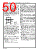
50 / 218 page  50 Real-Time Clock (RTC) and Advanced Power Control (APC) (Logical Device 2) www.national.com • An external clock may be connected to pin X1C. The time generation function divides the 32.768 KHz by 215 to derive a 1 Hz signal which serves as the input for time- keeping functions. Bits 6-4 of RTC Control Register A (CRA) control the activity and location of the divider chain in memory. Bits 3-0 of the CRA register select one of fifteen taps from the divider chain to be used as a periodic inter- rupt. See Section “RTC Control Register A (CRA), Index 0Ah” on page 52 for a description of divider configurations and rate selections. The divider chain is reset to 0 by bits 6-4 of the CRA regis- ter. An update occurs 500 msec after the divider chain is ac- tivated by setting normal operational mode (bits 6-4 of CRA = 010). The periodic flag becomes active one half of the pro- grammed period after the divider chain is activated. Figure 4-1 illustrates the internal and external circuitry that comprise the oscillator. FIGURE 4-1. Oscillator Internal and External Circuitry This oscillator is active under normal power or during power down. It stops only in the event of a power failure with the oscillator disabled (see “Oscillator Activity” on page 52), or when battery backup power drops below two volts. If oscillator input is from an external source, input should be driven rail to rail and should have a nominal 50% duty cycle. In this case, oscillator output X2C should be disabled. External capacitor values should be chosen to provide the manufacturer’s specified load capacitance for the crystal when combined with the parasitic capacitance of the trace, socket, and package, which can vary from 0 to 8 pF. The rule of thumb in choosing these capacitors is: CL = (C1 * C2) ÷ (C1 + C2) + CPARASITIC C2 > C1 C1 can be trimmed to achieve precisely 32768.0 Hz after in- sertion. Start-up time for this oscillator may vary from two to seven seconds due to the high Q of the crystal. The parameters below describe the crystal requirements: Parallel, resonant, tuning fork (N cut) or XY bar Q ≥ 35000 Load Capacitance (CL) 9 to 13 pF Accuracy and temperature coefficients are user defined. 20 M Ω Internal External REXT X1C X2C C1 C2 REXT = 120 KΩ C1 = 10 pF C2 = 33 pF CPARASITIC = 8 pF 4.1.2 Timekeeping Time is kept in BCD or binary format as determined by bit 2 (DM) of Control Register B (CRB). Either 12 or 24 hour rep- resentation for the hours can be maintained as determined by bit 1 of CRB. When changing formats, the time registers must be re-initialized to the corresponding data format. Daylight savings time and leap year exceptions are handled by the timekeeping function. When bit 0 (the Daylight Sav- ing Enable bit, DSE) of CRB is set to 1, time advances from 1:59:59 AM to 3:00:00 on the first Sunday in April, and changes from 1:59:59 to 1:00:00 on the last Sunday of Oc- tober. In leap years, February is extended to 29 days. Updating Timekeeping is performed by hardware, which updates a pre-programmed time value once per second. The pre-pro- grammed time values are written by the user to the following locations: The values for seconds, minutes, hours, day of week, date of month, month and year are located in the common stor- age area in all three memory banks (See Table 4-6 on page 64). The century value is located in Bank 1 (See Table 4-8 on page 65). Users must ensure that reading or writing to the time stor- age locations does not coincide with a system update of these locations, which would cause invalid and unpredict- able results. There are several ways to avoid this contention. Four op- tions follow: Method 1 - Set the SET bit (bit 7 of the CRB register) to 1. This takes a “snapshot” of the internal time registers and loads it into the user copy. If user copy registers have been updated, the user copy updates the internal regis- ters when the SET bit goes from 1 to 0. This mechanism enables loading new time parameters into the RTC. Method 2 - Access after detection of an Update-Ended in- terrupt. This implies that an update has just completed and there are 999 msec remaining until the next occurrence. Method 3 - Poll Update-In-Progress (UIP) (bit 7 in Control Register A). The update occurs 244 µsec after the update-in- progress bit goes high. Therefore if a 0 is read, there is a minimum of 244 µs in which the time is guaranteed to remain stable. Method 4 - Use a periodic interrupt to determine if an up- date cycle is in progress. The periodic interrupt is first set to a desired period. Pe- riodic interrupt appearance then indicates there is a pe- riod of (Period of periodic interrupt ÷ 2 + 244 µsec) remaining until another update occurs. |
|
Ligação URL |
| ALLDATASHEET é útil para você? [ DONATE ] |
Sobre Alldatasheet | Publicidade | Contato conosco | Privacy Policy | Link para a ficha técnica | roca de Link | Lista de Fabricantes All Rights Reserved©Alldatasheet.com |
| Russian : Alldatasheetru.com | Korean : Alldatasheet.co.kr | Spanish : Alldatasheet.es | French : Alldatasheet.fr | Italian : Alldatasheetit.com Portuguese : Alldatasheetpt.com | Polish : Alldatasheet.pl | Vietnamese : Alldatasheet.vn Indian : Alldatasheet.in | Mexican : Alldatasheet.com.mx | British : Alldatasheet.co.uk | New Zealand : Alldatasheet.co.nz |
|
Family Site : ic2ic.com |
icmetro.com |
 Portuguese ▼
 English
 Chinese
 German
 Japanese
 Russian
 Korean
 Spanish
 French
 Italian
 Portuguese
 Polish
 Vietnamese
 Indian
 Mexican
 British
 New Zealand