|
Os motores de busca de Datasheet de Componentes eletrônicos |
|
|
Os motores de busca de Datasheet de Componentes eletrônicos |
|
PC87307 Folha de dados(PDF) 60 Page - National Semiconductor (TI) |
|
|
|
|||||||||||||||||||||||||||||
PC87307 Folha de dados(HTML) 60 Page - National Semiconductor (TI) |
|
|
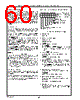
60 / 218 page  60 Real-Time Clock (RTC) and Advanced Power Control (APC) (Logical Device 2) www.national.com Predetermined Wake-Up The second, minute and hour values of the pre-determined wake-up times are contained in the Seconds Alarm, Min- utes Alarm and Hours Alarm registers, respectively (index- es 01h, 03h and 05h of banks 0, 1 and 2). The Day of Week, Date of Month, Month, Year and Century of the pre-deter- mined date is held in bank 2, registers indexes 43h-46h and 48h. These eight registers are compared with the corre- sponding Seconds, Minutes, Hours, Date of Week, Day of Month, Month and Year in all banks, register indexes 00, 02, 04, 06, 07, 08, 09 and Century register in bank 1, register index 48h. Ring Signal Event An incoming telephone call is an event that may activate a transfer from the Power-Off state to a Power-On state, in or- der to deal with the pending incoming voice, fax or modem communication. The part can detect a RING pulse falling edge or a RING pulse train with a frequency of at least 16 Hz, that lasts at least 0.19 seconds. During RING pulse train detection, the existence of falling edges on RING is monitored during time slots of 62.5 msec (16 Hz cycle time). A RING pulse train detect event occurs if falling edge(s) of RING were detected in three consecu- tive time slots, following a time slot in which no falling edge of RING was detected. This method of detecting a RING pulse train filters out (does not detect) a RING pulse train of less then 11 Hz, might de- tect a RING pulse train of 11 Hz to 16 Hz, and guarantees detection of a RING pulse train of at least 16 Hz. RI1,2 Event High to Low transitions on RI1 or RI2 indicate communica- tions activity on the UART inputs, and these conditions may be used as events to “wake-up” the system. NOTE: The APC can distinguish between two events of the same type if a minimum time of 2.5 periods of the 32Khz clock passed between their arrivals. Thus, if the APC detects an event, and another event of the same nature occurs once again in less than 70ms from the previous event, the APC might not detect the second event,i.e., the event will be lost. 4.5 APC REGISTERS The APC registers reside in the APC bank 2 memory. The RAM Lock register also resides in this bank. See Table 4-4 on page 55. The APC registers are not affected by system reset. They are initialized to 0 only when power is applied for the first time, i.e., application of one of the voltages VBAT or VCCH when no previous voltage was present. 4.5.1 APC Control Register 1 (APCR1), Index 40h FIGURE 4-11. APCR1 Register Bitmap Bit 0 - Reserved Reserved. Bit 1 - Switch Off Delay Option 0 - 4-5 seconds. 1 - 20-21 seconds. Bit 2 - POR Edge or Level Select 0 - Edge POR. 1 - Level POR. Once POR is asserted, it remains as- serted until cleared by Level POR Clear Command (bit 3). Bit 3 - Level POR Clear Command This is a write-only non-sticky bit. Read returns 0. 0 - Ignored. 1 - POR output signal is deactivated. Bit 4 - Mask ONCTL Activation if Power Fail (MOAP) 0 - When power returns, sets the system to the power state that existed when power failed. 1 - While the Power Failure bit (bit 7 of APCR1) is set, mask ONCTL activation, except as a result of a Switch On Event. Bit 5 - Software Off Command (SOC) This bit is write-only and non-sticky. Read returns 0. 0 - Ignored. 1 - ONCTL output signal is deactivated. Bit 6 - Fail-safe Timer Reset Command This bit is write-only and non-sticky. Read returns 0. 0 - Ignored. 1 - Fail-safe timer is stopped and reset. Bit 7 - Power Failure Set to 1 when RTC/APC switches from VCCH to VBAT. Cleared to 0 by writing 1 to this bit. Writing 0 to this bit has no effect. POR Edge or Level Select MOAP SOC Fail-safe Timer Reset Command Power Failure 76543210 Reserved Switch Off Delay Option Level POR Clear Command Index 40h Power-Up Required APC Control (APCR1) Reset Register 1 |
|
Ligação URL |
| ALLDATASHEET é útil para você? [ DONATE ] |
Sobre Alldatasheet | Publicidade | Contato conosco | Privacy Policy | Link para a ficha técnica | roca de Link | Lista de Fabricantes All Rights Reserved©Alldatasheet.com |
| Russian : Alldatasheetru.com | Korean : Alldatasheet.co.kr | Spanish : Alldatasheet.es | French : Alldatasheet.fr | Italian : Alldatasheetit.com Portuguese : Alldatasheetpt.com | Polish : Alldatasheet.pl | Vietnamese : Alldatasheet.vn Indian : Alldatasheet.in | Mexican : Alldatasheet.com.mx | British : Alldatasheet.co.uk | New Zealand : Alldatasheet.co.nz |
|
Family Site : ic2ic.com |
icmetro.com |
 Portuguese ▼
 English
 Chinese
 German
 Japanese
 Russian
 Korean
 Spanish
 French
 Italian
 Portuguese
 Polish
 Vietnamese
 Indian
 Mexican
 British
 New Zealand