|
Os motores de busca de Datasheet de Componentes eletrônicos |
|
|
Os motores de busca de Datasheet de Componentes eletrônicos |
|
PC87307 Folha de dados(PDF) 52 Page - National Semiconductor (TI) |
|
|
|
|||||||||||||||||||||||||||||
PC87307 Folha de dados(HTML) 52 Page - National Semiconductor (TI) |
|
|
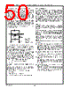
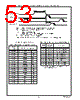
52 / 218 page  52 Real-Time Clock (RTC) and Advanced Power Control (APC) (Logical Device 2) www.national.com System Bus Lockout As the RTC switches to battery power all, input signals are locked out so that the internal registers can not be modified externally. Power Up Detection When system power is restored after a power failure, the power failure lock condition continues for a delay of 62 msec (minimum) to 125 msec (maximum) after the RTC switches from battery power to system power. The power failure lock condition is switched off immediately in the following situations: • If the Divider Chain Control bits (DV2-0, bits 6-4 in Con- trol Register A) specify any mode other than 010, 100 or 011, all input signals are enabled immediately upon de- tection of system voltage above that of the battery volt- age. • When battery voltage is below 1 volt and MR is 1, all in- put signals are enabled immediately upon detection of system voltage above that of battery voltage. This also initializes registers at indexes 00h through 0Dh. • If the VRT bit (bit 7 in Control Register D) is 0, all input signals are enabled immediately upon detection of sys- tem voltage above that of battery voltage. Oscillator Activity The RTC internal oscillator circuit is active whenever power is supplied to the RTC with the following exceptions: • Software wrote 000 or 001 to the Divider Chain Con- trol bits (DV2-0), i.e., bits 6-4, of Control Register A, and the RTC is supplied by VBAT, or • The RTC is supplied by V BAT and the VRT bit of Con- trol Register D is 0. These conditions disables the oscillator. When the oscillator becomes inactive, the APC is disabled. 4.1.4 Interrupt Handling The RTC logic device has a single Interrupt Request line, IRQ, which handles three interrupt conditions. The Periodic, Alarm, and Update-Ended interrupts are generated (IRQ is driven low) if the respective enable bits in Control Register B are set when an interrupt event occurs. Reading RTC Control Register C (CRC) clears all interrupt flags. Thus, it is recommended that when multiple interrupts are enabled, the interrupt service routine should first read and store the CRC register, then deal with all pending inter- rupts by referring to this stored status. If an interrupt is not serviced before a second occurrence of the same interrupt condition, the second interrupt event is lost. Figure 4-5 illustrates interrupt and status timing in the part. 4.2 THE RTC REGISTERS The RTC registers can be accessed at any time during non- battery backed operation. These registers cannot be written to before reading the VRT bit (bit 7 of the “RTC Control Reg- ister D (CRD), Index 0Dh” on page 55), thus preventing bank selection and other functions. The user must read the VRT bit as part of the startup activity. These registers are listed in Table 4-1 and described in de- tail in the sections that follow. 4.2.1 RTC Control Register A (CRA), Index 0Ah The CRA register controls periodic interrupt rate selection and bank selection. FIGURE 4-4. CRA Register Bitmap Bits 3-0 - Periodic Interrupt Rate Select (RS3-0) These read/write bits select one of fifteen output taps from the clock divider chain to control the rate of the pe- riodic interrupt. See Table 4-2 and Figure 4-5. Master reset does not affect these bits. Bits 6-4 - Divider Chain Control (DV2-0) These read/write bits control the configuration of the di- vider chain for timing generation and memory bank se- lection, as shown in Table 4-3. Master reset does not affect these bits. Bit 7 - Update in Progress (UIP) This read only bit is not affected by reset. 0 - An update will not occur within the next 244 µsec. Bit 7 (the SET bit) of Control Register B (CRB) is 1. 1 - Timing registers are updated within 244 µsec. RS2 DV0 DV2 UIP 76543210 Index 0Ah Power-Up Required RTC Control 0 0 0 0 0 1 0 0 RS0 RS3 DV1 RS1 (CRA) Reset Register A |
|
Ligação URL |
| ALLDATASHEET é útil para você? [ DONATE ] |
Sobre Alldatasheet | Publicidade | Contato conosco | Privacy Policy | Link para a ficha técnica | roca de Link | Lista de Fabricantes All Rights Reserved©Alldatasheet.com |
| Russian : Alldatasheetru.com | Korean : Alldatasheet.co.kr | Spanish : Alldatasheet.es | French : Alldatasheet.fr | Italian : Alldatasheetit.com Portuguese : Alldatasheetpt.com | Polish : Alldatasheet.pl | Vietnamese : Alldatasheet.vn Indian : Alldatasheet.in | Mexican : Alldatasheet.com.mx | British : Alldatasheet.co.uk | New Zealand : Alldatasheet.co.nz |
|
Family Site : ic2ic.com |
icmetro.com |
 Portuguese ▼
 English
 Chinese
 German
 Japanese
 Russian
 Korean
 Spanish
 French
 Italian
 Portuguese
 Polish
 Vietnamese
 Indian
 Mexican
 British
 New Zealand