|
Os motores de busca de Datasheet de Componentes eletrônicos |
|
|
Os motores de busca de Datasheet de Componentes eletrônicos |
|
PC87307 Folha de dados(PDF) 54 Page - National Semiconductor (TI) |
|
|
|
|||||||||||||||||||||||||||||
PC87307 Folha de dados(HTML) 54 Page - National Semiconductor (TI) |
|
|
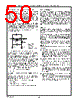
54 / 218 page  54 Real-Time Clock (RTC) and Advanced Power Control (APC) (Logical Device 2) www.national.com 4.2.2 RTC Control Register B (CRB), Index 0Bh This register enables the selection of various time and date options, as well as the use of interrupts. FIGURE 4-6. CRB Register Bitmap Bit 0 - Daylight Savings Enable (DSE) Master reset does not affect this read/write bit. 0 - Disables the daylight savings feature. 1 - Enables daylight savings feature, as follows: In the spring, time advances from 1:59:59 to 3:00:00 on the first Sunday in April. In the fall, time returns from 1:59:59 to 1:00:00 on the last Sunday in October. Bit 1 - 24 or 12 Hour Mode This is a read/write bit that is not affected by reset. 0 - Enables 12 hour format. 1 - Enables 24 hour format. Bit 2 - Data Mode (DM) This is a read/write bit that is not affected by reset. 0 - Enables BCD format. 1 - Enables binary format. Bit 3 - Unused This bit is defined as “Square Wave Enable” by the MC146818 and is not supported by the RTC. This bit is always read as 0. Bit 4 - Update-Ended Interrupt Enable (UIE) Master reset forces this read/write bit to 0. 0 - Disables generation of the Update-Ended interrupt. 1 - Enables generation of the Update-Ended interrupt. This interrupt is generated at the time an update occurs. Bit 5 - Alarm Interrupt Enable (AIE) Master reset forces this read/write bit to 0. 0 - Disables generation of the alarm interrupt. 1 - Enables generation of the Alarm interrupt. The alarm interrupt is generated immediately after a time update in which the Seconds, Minutes, and Hours time equal their respective alarm counter- parts. DM UIE AIE PIE SET 76543210 0 0 0 0 DSE 24 or 12 Hour Mode Unused 0 Index 0Bh Power-Up Required RTC Control (CRB) Reset Register B Bit 6 - Periodic Interrupt Enable (PIE) Master reset forces this read/write bit to 0. 0 - Disables generation of the Periodic interrupt. 1 - Enables generation of the Periodic interrupt. Bits 3- 0 of Control Register A (CRA) determine the rate of the Periodic interrupt. Bit 7 - Set Mode (SET) Master reset does not affect this read/write bit. 0 - The timing updates occur normally. 1 - The user copy of time is “frozen”, allowing the time registers to be accessed without regard for an oc- currence of an update. 4.2.3 RTC Control Register C (CRC), Index 0Ch This register indicates the status of interrupt request flags. FIGURE 4-7. CRC Register Bitmap Bits 3-0 - Reserved These bits are reserved and always return 0000. Bit 4 - Update-Ended Interrupt Flag (UF) Master reset forces this read-only bit to 0. In addition, this bit is reset to 0 when this register is read. 0 - No update has occurred since the last read. 1 - Time registers have been updated. Bit 5 - Alarm Interrupt Flag (AF) Master reset forces this read-only bit to 0. 0 - No alarm was detected since the last read. 1 - An alarm condition was detected. This bit is reset to 0 when this register is read. Bit 6 - Periodic Interrupt Flag (PF) Master reset forces this read-only bit to 0. In addition, this bit is reset to 0 when this register is read. 0 - Indicates no transition occurred on the selected tap since the last read. 1 - A transition occurred on the selected tap of the di- vider chain. UF AF PF IRQF 76543210 0 0 0 0 0 0 0 0 0 0 0 Reserved Index 0Ch Power-Up Required RTC Control (CRC) Reset Register C |
|
Ligação URL |
| ALLDATASHEET é útil para você? [ DONATE ] |
Sobre Alldatasheet | Publicidade | Contato conosco | Privacy Policy | Link para a ficha técnica | roca de Link | Lista de Fabricantes All Rights Reserved©Alldatasheet.com |
| Russian : Alldatasheetru.com | Korean : Alldatasheet.co.kr | Spanish : Alldatasheet.es | French : Alldatasheet.fr | Italian : Alldatasheetit.com Portuguese : Alldatasheetpt.com | Polish : Alldatasheet.pl | Vietnamese : Alldatasheet.vn Indian : Alldatasheet.in | Mexican : Alldatasheet.com.mx | British : Alldatasheet.co.uk | New Zealand : Alldatasheet.co.nz |
|
Family Site : ic2ic.com |
icmetro.com |
 Portuguese ▼
 English
 Chinese
 German
 Japanese
 Russian
 Korean
 Spanish
 French
 Italian
 Portuguese
 Polish
 Vietnamese
 Indian
 Mexican
 British
 New Zealand