|
Os motores de busca de Datasheet de Componentes eletrônicos |
|
|
Os motores de busca de Datasheet de Componentes eletrônicos |
|
PC87307 Folha de dados(PDF) 73 Page - National Semiconductor (TI) |
|
|
|
|||||||||||||||||||||||||||||
PC87307 Folha de dados(HTML) 73 Page - National Semiconductor (TI) |
|
|
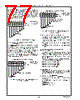
73 / 218 page  73 The Digital Floppy Disk Controller (FDC) (Logical Device 3) www.national.com Bit 4- Motor Enable 0 If four drives are supported (bit 7 of the SuperI/O FDC Configuration register at index F0h is 1), this bit may control the motor output signal for drive 0, depending on the remaining bits of this register. See Table 5-2. If two drives are supported (bit 7 of the SuperI/O FDC Configuration register at index F0h is 0), this bit controls the motor output signal for drive 0. 0 - The motor signal for drive 0 is not active. 1 - The motor signal for drive 0 is active. Bit 5 - Motor Enable 1 If four drives are supported (bit 7 of the SuperI/O FDC Configuration register at index F0h is 1), this bit may control the motor output signal for drive 0, depending on the remaining bits of this register. See Table 5-2. If two drives are supported (bit 7 of the SuperI/O FDC Configuration register at index F0h is 0), this bit controls the motor output signal for drive 1. 0 - The motor signal for drive 1 is not active. 1 - The motor signal for drive 1 is active. Bit 6 - Motor Enable 2 If drives 2 and 0 are exchanged (see logical drive ex- change bits 3,2 of TDR on page 74), or if four drives are supported (bit 7 of the SuperI/O FDC Configuration reg- ister at index F0h is 1), this bit controls the motor output signal for drive 2. See Table 5-2. 0 - The motor signal for drive 2 is not active. 1 - The motor signal for drive 2 is active. Bit 7 - Motor Enable 3 If four drives are supported (bit 7 of the SuperI/O FDC Configuration register at index F0h is 1), this bit may control the motor output signal for drive 3, depending on the remaining bits of this register. See Table 5-2. 0 - The motor signal for drive 3 is not active. 1 - The motor signal for drive 3 is active. 5.3.4 Tape Drive Register (TDR), Offset 03h The TDR register is a read/write register that acts as the Floppy Disk Controller’s (FDC) media and drive type regis- ter. The TDR functions differently, depending on the mode set by bit 6 the SuperI/O FDC Configuration register at index F0h. See “Bit 6 - TDR Register Mode” on page 37. AT Compatible TDR Mode In this mode, the TDR assigns a drive number to the tape drive support mode of the data separator. All other logical drives can be assigned as floppy drive support. Bits 7-2 are in TRI-STATE during read operations. Enhanced TDR Mode In this mode, all the bits of the TDR define operations with PS/2 floppy disk drives. FIGURE 5-8. TDR Register Bitmap, AT Compatible TDR Mode FIGURE 5-9. TDR Register Bitmap, Enhanced TDR Mode 76543210 Reset Required 0 0 1 Tape Drive Register (TDR) Offset 03h Tape Drive Select 1,0 AT Compatible TDR Mode TRI-STATE During Read Operations Not Used 76543210 Reset Required 0 0 1 Tape Drive Register (TDR) Offset 03h High Density Extra Density Tape Drive Select 1,0 Logical Drive Exchange Enhanced TDR Mode Drive ID1 Information Drive ID0 Information TABLE 5-4. TDR Bit Utilization and Reset Values in Different Drive Modes TDR Mode Bit 6 of SuperI/O FDC Configuration Register Bits of TDR Extra Density High Density Drive ID1 Drive ID0 Logical Drive Exchange Drive Select 7654 3 2 1 0 AT Compatible 0 Not used. Floated in TRI-STATE during read operations. 0 0 Enhanced 1 Not Reset Not Reset 1 1 0 0 0 0 |
|
Ligação URL |
| ALLDATASHEET é útil para você? [ DONATE ] |
Sobre Alldatasheet | Publicidade | Contato conosco | Privacy Policy | Link para a ficha técnica | roca de Link | Lista de Fabricantes All Rights Reserved©Alldatasheet.com |
| Russian : Alldatasheetru.com | Korean : Alldatasheet.co.kr | Spanish : Alldatasheet.es | French : Alldatasheet.fr | Italian : Alldatasheetit.com Portuguese : Alldatasheetpt.com | Polish : Alldatasheet.pl | Vietnamese : Alldatasheet.vn Indian : Alldatasheet.in | Mexican : Alldatasheet.com.mx | British : Alldatasheet.co.uk | New Zealand : Alldatasheet.co.nz |
|
Family Site : ic2ic.com |
icmetro.com |
 Portuguese ▼
 English
 Chinese
 German
 Japanese
 Russian
 Korean
 Spanish
 French
 Italian
 Portuguese
 Polish
 Vietnamese
 Indian
 Mexican
 British
 New Zealand