|
Os motores de busca de Datasheet de Componentes eletrônicos |
|
|
Os motores de busca de Datasheet de Componentes eletrônicos |
|
PC87307 Folha de dados(PDF) 92 Page - National Semiconductor (TI) |
|
|
|
|||||||||||||||||||||||||||||
PC87307 Folha de dados(HTML) 92 Page - National Semiconductor (TI) |
|
|
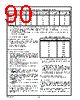
92 / 218 page  92 www.national.com Result Phase 5.7.5 The INVALID Command If an invalid command (illegal opcode byte in the command phase) is received by the Floppy Disk Controller (FDC), the controller responds with the result phase Status register 0 (ST0) in the result phase. See “Result Phase Status Regis- ter 0 (ST0)” on page 81 The controller does not generate an interrupt during this condition. Bits 7 and 6 in the MSR (see Section 5.3.6 page 75) are both set to 1, indicating to the microprocessor that the controller is in the result phase and the contents of ST0 must be read. Command Phase Execution Phase None. Result Phase The system reads the value 80h from ST0 indicating that an invalid command was received. 5.7.6 The LOCK Command The LOCK command can be used to keep the FIFO en- abled and to retain the values of some parameters after a software reset. After the command byte of the LOCK command is written, its result byte must be read before the opcode of the next command can be read. The LOCK command is not execut- ed until its result byte is read by the microprocessor. If the part is reset after the command byte of the LOCK com- mand is written but before its result byte is read, then the LOCK command is not executed. This prevents accidental execution of the LOCK command. 76543210 Result Phase Status Register 0 (ST0) Result Phase Status Register 1 (ST1) Result Phase Status Register 2 (ST2) Undefined Undefined Undefined Undefined 76543210 Invalid Opcodes 76543210 Result Phase Status Register 0 (STO) (80h) Command Phase Bit 7 - Control Reset Effect (LOCK) This bit determines how the FIFO, THRESH, and PRETRK bits in the CONFIGURE command and, the FWR, FRD, and BST bits in the MODE command are af- fected by a software reset. 0 -Set default values after a software reset. (Default) 1 - Values are unaffected by a software reset. Execution Phase Internal register is written. Result Phase Bit 4 - Control Reset Effect (LOCK) Same as bit 7 of opcode in command phase. 5.7.7 The MODE Command This command selects the special features of the controller. The bits in the command bytes of the MODE command are set to their default values after a hardware reset. Command Phase Second Command Phase Byte Bit 0 - Extended Track Range (ETR) This bit determines how the track number is stored. It is cleared to 0 after a software reset. 0 - Track number is stored as a standard 8-bit value compatible with the IBM, ISO, and Toshiba Perpen- dicular formats. This allows access of up to 256 tracks during a seek operation. (Default) 1 - Track number is stored as a 12-bit value. The upper four bits of the track value are stored in the upper four bits of the head number in the sector address field. This allows access of up to 4096 tracks during a seek operation. With this bit set, an extra byte is re- quired in the SEEK command phase and SENSE INTERRUPT result phase. 76543210 LOCK 0010100 76543210 0 0 0 LOCK 0000 76543210 00000001 TMR IAF IPS 0 LOW PWR 0 ETR FWR FRD BST R255 0000 DENSEL BFR WLD Head Settle Factor 00000000 |
|
Ligação URL |
| ALLDATASHEET é útil para você? [ DONATE ] |
Sobre Alldatasheet | Publicidade | Contato conosco | Privacy Policy | Link para a ficha técnica | roca de Link | Lista de Fabricantes All Rights Reserved©Alldatasheet.com |
| Russian : Alldatasheetru.com | Korean : Alldatasheet.co.kr | Spanish : Alldatasheet.es | French : Alldatasheet.fr | Italian : Alldatasheetit.com Portuguese : Alldatasheetpt.com | Polish : Alldatasheet.pl | Vietnamese : Alldatasheet.vn Indian : Alldatasheet.in | Mexican : Alldatasheet.com.mx | British : Alldatasheet.co.uk | New Zealand : Alldatasheet.co.nz |
|
Family Site : ic2ic.com |
icmetro.com |
 Portuguese ▼
 English
 Chinese
 German
 Japanese
 Russian
 Korean
 Spanish
 French
 Italian
 Portuguese
 Polish
 Vietnamese
 Indian
 Mexican
 British
 New Zealand