|
Os motores de busca de Datasheet de Componentes eletrônicos |
|
|
Os motores de busca de Datasheet de Componentes eletrônicos |
|
ADP1055ACPZ-R7 Folha de dados(PDF) 23 Page - Analog Devices |
|
|
|||||||||||||||||||||||||||||
ADP1055ACPZ-R7 Folha de dados(HTML) 23 Page - Analog Devices |
|
|
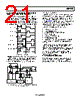
23 / 140 page  Data Sheet ADP1055 Rev. A | Page 23 of 140 ADCs AND TELEMETRY Two kinds of ADCs are used in the ADP1055: Low frequency (LF) Σ-Δ ADCs that runs at 1.56 MHz for accurate measurement and telemetry High frequency (HF) flash ADCs for the feedback and control loop Σ-Δ ADCs have a resolution of one bit and operate differently from traditional flash ADCs. The equivalent resolution obtain- able depends on how long the output bit stream of the Σ-Δ ADC is sampled. Σ-Δ ADCs also differ from Nyquist rate ADCs in that the quan- tization noise is not uniform across the frequency spectrum. At lower frequencies, the noise is lower, and at higher frequencies, the noise is higher (see Figure 28). Figure 28. Noise Performance for Nyquist Rate and Σ-Δ ADCs The low frequency ADC runs at approximately 1.56 MHz. For a specified bandwidth, the equivalent resolution can be calculated as follows: ln(1.56 MHz/BW)/ln2 = N bits For example, at a bandwidth of 95 Hz, the equivalent resolution/noise is ln(1.56 MHz/95)/ln2 = 14 bits At a bandwidth of 1.5 kHz, the equivalent resolution/noise is ln(1.56 MHz/1.5 kHz)/ln2 = 10 bits The ADC output information is available in the value registers (Register 0xFE96 to Register 0xFEA3) or through the PMBus READ_x commands, where x = VOUT, IOUT, and so on. ADCs FOR CURRENT SENSING The ADP1055 has two current sense inputs: CS1 and CS2±. These inputs sense, protect, and control the primary input current and the secondary output current information. The CS1 and CS2± inputs can be calibrated to reduce errors due to external components for accurate telemetry. CS1 ADC for Primary Side Current The CS1 pin is typically used for the monitoring and protection of the primary side current. The primary side current is sensed using a current transformer (CT). The input signal at the CS1 pin is fed into the CS1 ADC for current monitoring. Figure 29 shows the typical configuration for the current sense. The READ_IIN command reports the average input current; this reading is updated every 10.5 ms. Figure 29. Current Sense 1 (CS1) Operation CS2 ADC for Secondary Side Current The CS2+ and CS2− pins are differential inputs used for the monitoring and protection of the secondary side current. The ADP1055 supports differential sensing using low-side current sensing with two ranges for the ADC: 30 mV and 60 mV. The low input range is used to operate in level shifting mode, when the CS2 terminals are connected directly to the shunt resistor (see Figure 30). In this mode, a pair of internal resistors and current sources are used to perform the necessary level shifting. In this mode, only low-side current sensing is possible, and the ADC range is programmable to 30 mV or 60 mV. Figure 30. Differential Low-Side Sensing FREQUENCY NYQUIST ADC NOISE Σ-∆ ADC NOISE CS1 1kΩ 10Ω I = 100mA I = 10A VIN OUTA OUTB OUTC OUTD ADC 12 BITS VREF FAST OCP 1:100 1V CS2– AGND CS2 RANGES RANGE1 = 0mV TO 30mV RANGE2 = 0mV TO 60mV CS2 FAST OCP 0mV TO 60mV/6 BITS (STEP SIZE 0.952mV) CS2 ADC IOUT_OC_LIMIT IOUT_UC_LIMIT CS2 IREV LIMIT 0mV TO –30mV (STEP SIZE 0.4762mV) ILOAD ADP1055 CS2+ |
|
Ligação URL |
| ALLDATASHEET é útil para você? [ DONATE ] |
Sobre Alldatasheet | Publicidade | Contato conosco | Privacy Policy | Link para a ficha técnica | roca de Link | Lista de Fabricantes All Rights Reserved©Alldatasheet.com |
| Russian : Alldatasheetru.com | Korean : Alldatasheet.co.kr | Spanish : Alldatasheet.es | French : Alldatasheet.fr | Italian : Alldatasheetit.com Portuguese : Alldatasheetpt.com | Polish : Alldatasheet.pl | Vietnamese : Alldatasheet.vn Indian : Alldatasheet.in | Mexican : Alldatasheet.com.mx | British : Alldatasheet.co.uk | New Zealand : Alldatasheet.co.nz |
|
Family Site : ic2ic.com |
icmetro.com |
 Portuguese ▼
 English
 Chinese
 German
 Japanese
 Russian
 Korean
 Spanish
 French
 Italian
 Portuguese
 Polish
 Vietnamese
 Indian
 Mexican
 British
 New Zealand