|
Os motores de busca de Datasheet de Componentes eletrônicos |
|
|
Os motores de busca de Datasheet de Componentes eletrônicos |
|
AD9775 Folha de dados(PDF) 29 Page - Analog Devices |
|
|
|||||||||||||||||||||||||||||
AD9775 Folha de dados(HTML) 29 Page - Analog Devices |
|
|
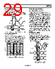
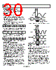
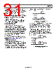
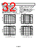
29 / 56 page  AD9775 Rev. E | Page 29 of 56 DATACLK INVERSION (Control Register 0x02, Bit 4) By programming this bit, the DATACLK signal shown in Figure 52 can be inverted. With inversion enabled, tOD refers to the time between the rising edge of CLKIN and the falling edge of DATACLK. No other effect on timing occurs. tOD tS tOD = 1.5ns (MIN) TO 2.5ns (MAX) tS = 0.0ns (MIN) tH = 2.5ns (MIN) tH CLKIN DATACLK DATA AT PORTS 1 AND 2 Figure 52. Timing Requirements in Two-Port Input Mode, with PLL Enabled DATACLK DRIVER STRENGTH (Control Register 0x02, Bit 5) The DATACLK output driver strength is capable of driving >10 mA into a 330 Ω load while providing a rise time of 3 ns. Figure 53 shows DATACLK driving a 330 Ω resistive load at a frequency of 50 MHz. By enabling the drive strength option (Control Register 0x02, Bit 5), the amplitude of DATACLK under these conditions increases by approximately 200 mV. –0.5 0 0.5 1.0 1.5 2.0 2.5 3.0 0 102030 40 50 TIME (ns) DELTA APPROX. 2.8ns Figure 53. DATACLK Driver Capability into 330 Ω at 50 MHz PLL ENABLED, ONE-PORT MODE (Control Register 0x02, Bit 6 to Bit 1 and Control Register 0x04, Bit 7 to Bit 1) In one-port mode, the I and Q channels receive their data from an interleaved stream at digital input Port 1. The function of Pin 32 is defined as an output (ONEPORTCLK) that generates a clock at the interleaved data rate, which is 2× the internal input data rate of the I and Q channels. The frequency of CLKIN is equal to the internal input data rate of the I and Q channels. The selection of the data for the I or the Q channel is determined by the state of the logic level at Pin 31 (IQSEL when the AD9775 is in one-port mode) on the rising edge of ONEPORTCLK. Under these conditions, IQSEL = 0 latches the data into the I channel on the clock rising edge, while IQSEL = 1 latches the data into the Q channel. It is possible to invert the I and Q selection by setting Control Register 0x02, Bit 1 to the invert state (Logic 1). Figure 54 illustrates the timing requirements for the data inputs as well as the IQSEL input. Note that the 1× interpolation rate is not available in the one-port mode. The DAC output sample rate in one-port mode is equal to CLKIN multiplied by the interpolation rate. If zero stuffing is used, another factor of 2 must be included to calculate the DAC sample rate. ONEPORTCLK INVERSION (Control Register 0x02, Bit 2) By programming this bit, the ONEPORTCLK signal shown in Figure 54 can be inverted. With inversion enabled, tOD refers to the delay between the rising edge of the external clock and the falling edge of ONEPORTCLK. The setup and hold times, tS and tH, are with respect to the falling edge of ONEPORTCLK. There is no other effect on timing. tOD tS tIQS tIQH tOD = 4.0ns (MIN) TO 5.5ns (MAX) tS = 3.0ns (MIN) tH = –0.5ns (MIN) tIQS = 3.5ns (MIN) tIQH = –1.5ns (MIN) tH CLKIN ONEPORTCLK IQSEL I AND Q INTERLEAVED INPUT DATA AT PORT 1 Figure 54. Timing Requirements in One-Port Input Mode with the PLL Enabled |
|
Ligação URL |
| ALLDATASHEET é útil para você? [ DONATE ] |
Sobre Alldatasheet | Publicidade | Contato conosco | Privacy Policy | Link para a ficha técnica | roca de Link | Lista de Fabricantes All Rights Reserved©Alldatasheet.com |
| Russian : Alldatasheetru.com | Korean : Alldatasheet.co.kr | Spanish : Alldatasheet.es | French : Alldatasheet.fr | Italian : Alldatasheetit.com Portuguese : Alldatasheetpt.com | Polish : Alldatasheet.pl | Vietnamese : Alldatasheet.vn Indian : Alldatasheet.in | Mexican : Alldatasheet.com.mx | British : Alldatasheet.co.uk | New Zealand : Alldatasheet.co.nz |
|
Family Site : ic2ic.com |
icmetro.com |
 Portuguese ▼
 English
 Chinese
 German
 Japanese
 Russian
 Korean
 Spanish
 French
 Italian
 Portuguese
 Polish
 Vietnamese
 Indian
 Mexican
 British
 New Zealand