|
Os motores de busca de Datasheet de Componentes eletrônicos |
|
|
Os motores de busca de Datasheet de Componentes eletrônicos |
|
AD9775 Folha de dados(PDF) 37 Page - Analog Devices |
|
|
|||||||||||||||||||||||||||||
AD9775 Folha de dados(HTML) 37 Page - Analog Devices |
|
|
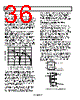
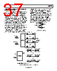
37 / 56 page  AD9775 Rev. E | Page 37 of 56 COMPLEX MODULATION AND IMAGE REJECTION OF BASEBAND SIGNALS In traditional transmit applications, a two-step upconversion is done in which a baseband signal is modulated by one carrier to an intermediate frequency (IF) and then modulated a second time to the transmit frequency. Although this approach has several benefits, a major drawback is that two images are created near the transmit frequency. Only one image is needed, the other being an exact duplicate. Unless the unwanted image is filtered, typically with analog components, transmit power is wasted and the usable bandwidth available in the system is reduced. A more efficient method of suppressing the unwanted image can be achieved by using a complex modulator followed by a quadrature modulator. Figure 78 is a block diagram of a quadrature modulator. Note that it is in fact the real output half of a complex modulator. The complete upconversion can actually be referred to as two complex upconversion stages, the real output of which becomes the transmitted signal. The entire upconversion, from baseband to transmit frequency, is represented graphically in Figure 79. The resulting spectrum shown in Figure 79 represents the complex data consisting of the baseband real and imaginary channels, now modulated onto orthogonal (cosine and negative sine) carriers at the transmit frequency. It is important to remember that in this application (two baseband data channels) the image rejection is not dependent on the data at either of the AD9775 input channels. In fact, image rejection still occurs with either one or both of the AD9775 input channels active. Note that by changing the sign of the sinusoidal multiplying term in the complex modulator, the upper sideband image could have been suppressed while passing the lower one. This is easily done in the AD9775 by selecting the e+jωt bit (Register 0x01, Bit 1). In purely complex terms, Figure 79 represents the two-stage upconversion from complex baseband to carrier. INPUT (REAL) OUTPUT INPUT (IMAGINARY) 90 ° COS ωt SIN ωt Figure 78. Quadrature Modulator REAL CHANNEL (OUT) IMAGINARY CHANNEL (OUT) A/2 –B/2J B/2J –A/2J A/2J –FC1 FC FC –FC –FC –FC FC –FC A/2 B/2 B/2 COMPLEX MODULATOR TO QUADRATURE MODULATOR REAL CHANNEL (IN) IMAGINARY CHANNEL (IN) A DC B DC A/4 + B/4J A/4 – B/4J A/4 + B/4J A/4 – B/4J –A/4 – B/4J A/2 + B/2J A/2 – B/2J A/4 – B/4J A/4 + B/4J –A/4 + B/4J –FQ – FC –FQ + FC –FQ2 –FQ FQ –FQ FQ FQ – FC FQ + FC FQ QUADRATURE MODULATOR OUT REAL IMAGINARY REJECTED IMAGES 1FC = COMPLEX MODULATION FREQUENCY 2FQ = QUADRATURE MODULATION FREQUENCY Figure 79. Two-Stage Upconversion and Resulting Image Rejection |
|
Ligação URL |
| ALLDATASHEET é útil para você? [ DONATE ] |
Sobre Alldatasheet | Publicidade | Contato conosco | Privacy Policy | Link para a ficha técnica | roca de Link | Lista de Fabricantes All Rights Reserved©Alldatasheet.com |
| Russian : Alldatasheetru.com | Korean : Alldatasheet.co.kr | Spanish : Alldatasheet.es | French : Alldatasheet.fr | Italian : Alldatasheetit.com Portuguese : Alldatasheetpt.com | Polish : Alldatasheet.pl | Vietnamese : Alldatasheet.vn Indian : Alldatasheet.in | Mexican : Alldatasheet.com.mx | British : Alldatasheet.co.uk | New Zealand : Alldatasheet.co.nz |
|
Family Site : ic2ic.com |
icmetro.com |
 Portuguese ▼
 English
 Chinese
 German
 Japanese
 Russian
 Korean
 Spanish
 French
 Italian
 Portuguese
 Polish
 Vietnamese
 Indian
 Mexican
 British
 New Zealand