|
Os motores de busca de Datasheet de Componentes eletrônicos |
|
|
Os motores de busca de Datasheet de Componentes eletrônicos |
|
AD9775 Folha de dados(PDF) 38 Page - Analog Devices |
|
|
|||||||||||||||||||||||||||||
AD9775 Folha de dados(HTML) 38 Page - Analog Devices |
|
|
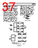
38 / 56 page  AD9775 Rev. E | Page 38 of 56 IMAGE REJECTION AND SIDEBAND SUPPRESSION OF MODULATED CARRIERS As shown in Figure 79, image rejection can be achieved by applying baseband data to the AD9775 and following the AD9775 with a quadrature modulator. To process multiple carriers while still maintaining image reject capability, each carrier must be complex modulated. As Figure 80 shows, single or multiple complex modulators can be used to synthesize complex carriers. These complex carriers are then summed and applied to the real and imaginary inputs of the AD9775. A system in which multiple baseband signals are complex modulated and then applied to the AD9775 real and imaginary inputs followed by a quadrature modulator is shown in Figure 82, which also describes the transfer function of this system and the spectral output. Note the similarity of the transfer functions given in Figure 82 and Figure 80. Figure 82 adds an additional complex modulator stage for the purpose of summing multiple carriers at the AD9775 inputs. Also, as in Figure 79, the image rejection is not dependent on the real or imaginary baseband data on any channel. Image rejection on a channel occurs if either the real or imaginary data, or both, is present on the baseband channel. It is important to remember that the magnitude of a complex signal can be 1.414× the magnitude of its real or imaginary components. Due to this 3 dB increase in signal amplitude, the real and imaginary inputs to the AD9775 must be kept at least 3 dB below full scale when operating with the complex modu- lator. Overranging in the complex modulator results in severe distortion at the DAC output. COMPLEX BASEBAND SIGNAL OUTPUT = REAL = REAL FREQUENCY 1 1/2 1/2 – ω1– ω2DC × ej(ω1 + ω2)t ω1 + ω2 Figure 80. Two-Stage Complex Upconversion BASEBAND CHANNEL 1 REAL INPUT BASEBAND CHANNEL 2 REAL INPUT BASEBAND CHANNEL N REAL INPUT IMAGINARY INPUT IMAGINARY INPUT IMAGINARY INPUT COMPLEX MODULATOR 1 COMPLEX MODULATOR 2 COMPLEX MODULATOR N R(1) R(1) R(2) R(2) R(N) R(N) MULTICARRIER REAL OUTPUT = R(1) + R(2) + . . .R(N) (TO REAL INPUT OF AD9775) MULTICARRIER IMAGINARY OUTPUT = I(1) + I(2) + . . .I(N) (TO IMAGINARY INPUT OF AD9775) R(N) = REAL OUTPUT OF N I(N) = IMAGINARY OUTPUT OF N Figure 81. Synthesis of Multicarrier Complex Signal MULTIPLE BASEBAND CHANNELS MULTIPLE COMPLEX MODULATORS FREQUENCY = ω 1, ω2...ωN REAL IMAGINARY REAL OUTPUT = REAL IMAGINARY REAL REAL IMAGINARY AD9775 COMPLEX MODULATOR FREQUENCY = ω C QUADRATURE MODULATOR FREQUENCY = ω Q COMPLEX BASEBAND SIGNAL REJECTED IMAGES DC × ej(ωN + ωC + ωQ)t – ω 1 – ωC – ωQ ω 1 + ωC + ωQ Figure 82. Image Rejection with Multicarrier Signals |
|
Ligação URL |
| ALLDATASHEET é útil para você? [ DONATE ] |
Sobre Alldatasheet | Publicidade | Contato conosco | Privacy Policy | Link para a ficha técnica | roca de Link | Lista de Fabricantes All Rights Reserved©Alldatasheet.com |
| Russian : Alldatasheetru.com | Korean : Alldatasheet.co.kr | Spanish : Alldatasheet.es | French : Alldatasheet.fr | Italian : Alldatasheetit.com Portuguese : Alldatasheetpt.com | Polish : Alldatasheet.pl | Vietnamese : Alldatasheet.vn Indian : Alldatasheet.in | Mexican : Alldatasheet.com.mx | British : Alldatasheet.co.uk | New Zealand : Alldatasheet.co.nz |
|
Family Site : ic2ic.com |
icmetro.com |
 Portuguese ▼
 English
 Chinese
 German
 Japanese
 Russian
 Korean
 Spanish
 French
 Italian
 Portuguese
 Polish
 Vietnamese
 Indian
 Mexican
 British
 New Zealand