|
Os motores de busca de Datasheet de Componentes eletrônicos |
|
|
Os motores de busca de Datasheet de Componentes eletrônicos |
|
AD6677 Folha de dados(PDF) 42 Page - Analog Devices |
|
|
|||||||||||||||||||||||||||||
AD6677 Folha de dados(HTML) 42 Page - Analog Devices |
|
|
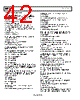
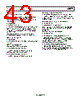
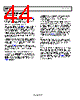
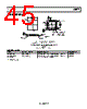
42 / 48 page  AD6677 Data Sheet Rev. C | Page 42 of 48 Bit 0—JESD204B link power-down If Bit 0 is set high, the serial transmit link is held in reset with the clock gated off. The JESD204B transmitter must be powered down when changing any of the link configuration bits. JESD204B Link Control 2 (Address 0x60) Bits[7:5]—Reserved; set to 0 Bit 4—SYNCINB± logic type 0 = LVDS differential pair SYNCINB± input (default). 1 = CMOS single-ended SYNCINB± using the SYNCINB+ input. If operating in this mode, leave the SYNCINB− floating. Bit 3—Open Bit 2—Reserved; set to 0 Bit 1—Invert transmit bits Setting this bit inverts the 10 serial output bits. This effectively inverts the output signals. Bit 0—Reserved; set to 0 JESD204B Link Control 3 (Address 0x61) Bit [7:6]—Reserved; set to 0 Bits[5:4]—Test data injection point 01 = 10-bit test generation data injected at output of 8B/10B encoder (at input to PHY). 10 = 8-bit test generation data injected at input of scrambler. Bits[3:0]—JESD204B Test Mode Patterns 0000 = normal operation (test mode disabled). 0001 = alternating checkerboard. 0010 = 1/0 word toggle. 0011 = PN23 sequence. 0100 = PN9 sequence. 0101 = continuous/repeat user test mode. The most significant bits from the user patterns (1, 2, 3, 4) are placed on the output for one clock cycle and then the output user patterns are repeated (1, 2, 3, 4, 1, 2, 3, 4, 1, 2, 3, 4….). 0110 = single user test mode. The most significant bits from the user patterns (1, 2, 3, 4) are placed on the output for one clock cycle and then all zeros are output (output user patterns 1, 2, 3, 4; then output all zeros). 0111 = reserved. 1100 = PN7 sequence. 1101 = PN15 sequence. Others = unused. JESD204B Device Identification (DID) Configuration (Address 0x64) Bits[7:0]—JESD204B device identification (DID) value JESD204B Bank Identification (BID) Configuration (Address 0x65) Bits[7:4]—Open Bits[3:0]—JESD204B bank identification (BID) value JESD204B Lane Identification (LID) Configuration (Address 0x67) Bits[7:5]—Open Bits[4:0]—JESD204B lane identification (LID) value JESD204B Scrambler (SCR) and Lane (L) Configuration (Address 0x6E) Bit 7—JESD204B scrambling (SCR) When this bit is set to low, it disables the scrambler (SCR = 0). When this bit is set to high, it enables the scrambler (SCR = 1). Bits[6:5]—Open Bits[4:0]—JESD204B number of lanes 0 = one lane per link (L = 1). JESD204B Parameters, F (Address 0x6F, Read Only) Bits[7:0]—JESD204B number of octets per frame (F) The readback from this register is calculated from the following equation: F = (M × 2)/L. The valid value for F is F = 2, with M = 1 and L = 1. JESD204B Parameters, K (Address 0x70) Bits[7:0]—JESD204B number of frames per multiframe (K) This register sets the K value for the JESD204B interface which defines the number of frames per multiframe. The value must be a multiple of 4. JESD204B Parameters, M (Address 0x71) Bit [7:0]—JESD204B number of converters (M) 0 = link connected to one ADC. Only primary input used (M = 1). JESD204B Parameters, N/CS (Address 0x72) Bits[7:6]—Number of control bits (CS) 00 = no control bits sent per sample (CS = 0). 01 = one control bit sent per sample—overrange bit enabled (CS = 1). 10 = two control bits sent per sample—overflow/underflow bits enabled (CS = 2). Bit [5:4]—Open Bits [3:0]—ADC converter resolution (N) Read only bits showing the converter resolution (reads back 13 (0xD) for 14-bit resolution). JESD204B Parameters, Subclass/N’ (Address 0x73) Bit 7—Reserved Bits[6:5]—JESD204B subclass When Bits[6:5] are 00, the device operates in Subclass 0 mode, and when Bits[6:5] are 01, the device operates in Subclass 1 mode. |
|
Ligação URL |
| ALLDATASHEET é útil para você? [ DONATE ] |
Sobre Alldatasheet | Publicidade | Contato conosco | Privacy Policy | Link para a ficha técnica | roca de Link | Lista de Fabricantes All Rights Reserved©Alldatasheet.com |
| Russian : Alldatasheetru.com | Korean : Alldatasheet.co.kr | Spanish : Alldatasheet.es | French : Alldatasheet.fr | Italian : Alldatasheetit.com Portuguese : Alldatasheetpt.com | Polish : Alldatasheet.pl | Vietnamese : Alldatasheet.vn Indian : Alldatasheet.in | Mexican : Alldatasheet.com.mx | British : Alldatasheet.co.uk | New Zealand : Alldatasheet.co.nz |
|
Family Site : ic2ic.com |
icmetro.com |
 Portuguese ▼
 English
 Chinese
 German
 Japanese
 Russian
 Korean
 Spanish
 French
 Italian
 Portuguese
 Polish
 Vietnamese
 Indian
 Mexican
 British
 New Zealand