|
Os motores de busca de Datasheet de Componentes eletrônicos |
|
|
Os motores de busca de Datasheet de Componentes eletrônicos |
|
UCD3138064ARGCR.A Folha de dados(PDF) 55 Page - Texas Instruments |
|
|
|||||||||||||||||||||||||||||
UCD3138064ARGCR.A Folha de dados(HTML) 55 Page - Texas Instruments |
|
|
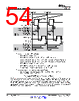
55 / 84 page  Start of Period Period Counter Start of Period Period Sample Trigger 1 DPWM Output A Filter Duty/2 (High Resolution) Period/2 DPWM Output B Blanking A Begin Blanking A End Blanking B Begin Blanking B End Phase Trigger Sample Trigger 2 To Other Modules To Other Modules Triangular Mode Closed Loop Filter controlled edge Cycle Adjust A (High Resolution) Cycle Adjust B (High Resolution) 55 UCD3138064A www.ti.com SLUSCA5B – DECEMBER 2015 – REVISED JANUARY 2017 Submit Documentation Feedback Product Folder Links: UCD3138064A Detailed Description Copyright © 2015–2017, Texas Instruments Incorporated 6.5.2 Triangular Mode Triangular mode provides a stable phase shift in interleaved PFC and similar topologies. In this case, the PWM pulse is centered in the middle of the period, rather than starting at one end or the other. In Triangular Mode, only DPWM-B is available. A diagram for Triangular Mode is shown in Figure 6-30: Events which change with DPWM mode: DPWM A Rising Edge = None DPWM A Falling Edge = None Adaptive Sample Trigger None DPWM B Rising Edge = Period/2 – Filter Duty/2 + Cycle Adjust A DPWM B Falling Edge = Period/2 + Filter Duty/2 + Cycle Adjust B Phase Trigger = Phase Trigger Register value or Filter Duty Events always set by their registers, regardless of mode: Sample Trigger 1, Sample Trigger 2, Blanking A Begin, Blanking A End, Blanking B Begin, Blanking B End Figure 6-30. Triangular Mode All edges are dynamic in triangular mode, so fixed blanking is not that useful. The adaptive sample trigger is not needed. It is very easy to put a fixed sample trigger exactly in the center of the FET on-time, because the center of the on-time does not move in this mode. 6.5.3 Leading Edge Mode Leading edge mode is similar to Normal mode, reversed in time. The DPWM A falling edge is fixed, and the rising edge moves to the left, or backwards in time, as the filter output increases. The DPWM B falling edge stays ahead of the DPWMA rising edge by a fixed dead time. A diagram of the Leading Edge Mode is shown in Figure 6-31: |
|
Ligação URL |
| ALLDATASHEET é útil para você? [ DONATE ] |
Sobre Alldatasheet | Publicidade | Contato conosco | Privacy Policy | Link para a ficha técnica | roca de Link | Lista de Fabricantes All Rights Reserved©Alldatasheet.com |
| Russian : Alldatasheetru.com | Korean : Alldatasheet.co.kr | Spanish : Alldatasheet.es | French : Alldatasheet.fr | Italian : Alldatasheetit.com Portuguese : Alldatasheetpt.com | Polish : Alldatasheet.pl | Vietnamese : Alldatasheet.vn Indian : Alldatasheet.in | Mexican : Alldatasheet.com.mx | British : Alldatasheet.co.uk | New Zealand : Alldatasheet.co.nz |
|
Family Site : ic2ic.com |
icmetro.com |
 Portuguese ▼
 English
 Chinese
 German
 Japanese
 Russian
 Korean
 Spanish
 French
 Italian
 Portuguese
 Polish
 Vietnamese
 Indian
 Mexican
 British
 New Zealand