|
Os motores de busca de Datasheet de Componentes eletrônicos |
|
|
Os motores de busca de Datasheet de Componentes eletrônicos |
|
UCD3138064ARGCR Folha de dados(PDF) 25 Page - Texas Instruments |
|
|
|
|||||||||||||||||||||||||||||
UCD3138064ARGCR Folha de dados(HTML) 25 Page - Texas Instruments |
|
|
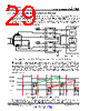
25 / 83 page  EAP0 EAN0 DAC0 EADC 4 bit dithering gives 14 bits of effective resolution 97.65625 V/LSB effective resolution X 6 bit ADC 8mV/LSB Signed 9 bit result (error) 1 mV /LSB AFE_GAIN 10 bit DAC 1.5625mV/LSB Value Dither CPCC Filter x Ramp SAR/Prebias Absolute Value Calculation Averaging 10 bit result 1.5625mV/LSB 2 3-AFE_GAIN Peak Current Mode Comparator Peak Current Detected A0 2 AFE_GAIN 25 UCD3138064A www.ti.com SLUSCA5A – DECEMBER 2015 – REVISED AUGUST 2016 Submit Documentation Feedback Product Folder Links: UCD3138064A Detailed Description Copyright © 2015–2016, Texas Instruments Incorporated Figure 6-3. Front End Module 6.4.2.1.2 DPWM Module The DPWM module represents one complete DPWM channel with 2 independent outputs, A and B. Multiple DPWM modules within the UCD3138x system can be configured to support all key power topologies. DPWM modules can be used as independent DPWM outputs, each controlling one power supply output voltage rail. It can also be used as a synchronized DPWM—with user selectable phase shift between the DPWM channels to control power supply outputs with multiphase or interleaved DPWM configurations. The output of the filter feeds the high resolution DPWM module. The DPWM module produces the pulse width modulated outputs for the power stage switches. The filter calculates the necessary duty ratio as a 24-bit number in Q23 fixed point format (23 bit integer with 1 sign bit). This represents a value within the range 0.0 to 1.0. This duty ratio value is used to generate the corresponding DPWM output ON time. The resolution of the DPWM ON time is 250 psec. Each DPWM module can be synchronized to another module or to an external synchronization signal. An input SYNC signal causes a DPWM ramp timer to reset. The SYNC signal outputs—from each of the four DPWM modules—occur when the ramp timer crosses a programmed threshold. This allows the phase of the DPWM outputs for multiple power stages to be tightly controlled. The DPWM logic takes the output of the filter and converts it into the correct DPWM output for several power supply topologies. It provides for programmable dead times and cycle adjustments for current balancing between phases. It controls the triggering of the EADC. It can synchronize to other DPWMs or to external sources. It can provide synchronization information to other DPWMs or to external recipients. In addition, it interfaces to several fault handling circuits. Some of the control for these fault handling circuits is in the DPWM registers. Fault handling is covered in the Fault Mux section. |
|
Ligação URL |
| ALLDATASHEET é útil para você? [ DONATE ] |
Sobre Alldatasheet | Publicidade | Contato conosco | Privacy Policy | Link para a ficha técnica | roca de Link | Lista de Fabricantes All Rights Reserved©Alldatasheet.com |
| Russian : Alldatasheetru.com | Korean : Alldatasheet.co.kr | Spanish : Alldatasheet.es | French : Alldatasheet.fr | Italian : Alldatasheetit.com Portuguese : Alldatasheetpt.com | Polish : Alldatasheet.pl | Vietnamese : Alldatasheet.vn Indian : Alldatasheet.in | Mexican : Alldatasheet.com.mx | British : Alldatasheet.co.uk | New Zealand : Alldatasheet.co.nz |
|
Family Site : ic2ic.com |
icmetro.com |
 Portuguese ▼
 English
 Chinese
 German
 Japanese
 Russian
 Korean
 Spanish
 French
 Italian
 Portuguese
 Polish
 Vietnamese
 Indian
 Mexican
 British
 New Zealand