|
Os motores de busca de Datasheet de Componentes eletrônicos |
|
|
Os motores de busca de Datasheet de Componentes eletrônicos |
|
DSPIC30F6010 Folha de dados(PDF) 14 Page - Microchip Technology |
|
|
|||||||||||||||||||||||||||||
DSPIC30F6010 Folha de dados(HTML) 14 Page - Microchip Technology |
|
|
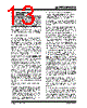
14 / 222 page  dsPIC30F6010 DS70119E-page 12 © 2006 Microchip Technology Inc. 2.2 Programmer’s Model The programmer’s model is shown in Figure 2-1 and consists of 16x16-bit working registers (W0 through W15), 2x40-bit accumulators (ACCA and ACCB), STATUS register (SR), Data Table Page register (TBLPAG), Program Space Visibility Page register (PSVPAG), DO and REPEAT registers (DOSTART, DOEND, DCOUNT and RCOUNT), and Program Counter (PC). The working registers can act as data, address or offset registers. All registers are memory mapped. W0 acts as the W register for file register addressing. Some of these registers have a shadow register asso- ciated with each of them, as shown in Figure 2-1. The shadow register is used as a temporary holding register and can transfer its contents to or from its host register upon the occurrence of an event. None of the shadow registers are accessible directly. The following rules apply for transfer of registers into and out of shadows. • PUSH.S and POP.S W0, W1, W2, W3, SR (DC, N, OV, Z and C bits only) are transferred. • DO instruction DOSTART, DOEND, DCOUNT shadows are pushed on loop start, and popped on loop end. When a byte operation is performed on a working reg- ister, only the Least Significant Byte (LSB) of the target register is affected. However, a benefit of memory mapped working registers is that both the Least and Most Significant Bytes can be manipulated through byte wide data memory space accesses. 2.2.1 SOFTWARE STACK POINTER/ FRAME POINTER The dsPIC® DSC devices contain a software stack. W15 is the dedicated software Stack Pointer (SP), and will be automatically modified by exception processing and subroutine calls and returns. However, W15 can be referenced by any instruction in the same manner as all other W registers. This simplifies the reading, writing and manipulation of the Stack Pointer (e.g., creating stack frames). W15 is initialized to 0x0800 during a Reset. The user may reprogram the SP during initialization to any location within data space. W14 has been dedicated as a Stack Frame Pointer as defined by the LNK and ULNK instructions. However, W14 can be referenced by any instruction in the same manner as all other W registers. 2.2.2 STATUS REGISTER The dsPIC DSC core has a 16-bit Status Register (SR), the LSB of which is referred to as the SR Low Byte (SRL) and the Most Significant Byte (MSB) as the SR High Byte (SRH). See Figure 2-1 for SR layout. SRL contains all the MCU ALU operation status flags (including the Z bit), as well as the CPU Interrupt Prior- ity Level status bits, IPL<2:0>, and the REPEAT active status bit, RA. During exception processing, SRL is concatenated with the MSB of the PC to form a com- plete word value which is then stacked. The upper byte of the SR register contains the DSP Adder/Subtracter status bits, the DO Loop Active bit (DA) and the Digit Carry (DC) status bit. 2.2.3 PROGRAM COUNTER The Program Counter is 23 bits wide. Bit 0 is always clear. Therefore, the PC can address up to 4M instruction words. Note: In order to protect against misaligned stack accesses, W15<0> is always clear. |
|
Ligação URL |
| ALLDATASHEET é útil para você? [ DONATE ] |
Sobre Alldatasheet | Publicidade | Contato conosco | Privacy Policy | Link para a ficha técnica | roca de Link | Lista de Fabricantes All Rights Reserved©Alldatasheet.com |
| Russian : Alldatasheetru.com | Korean : Alldatasheet.co.kr | Spanish : Alldatasheet.es | French : Alldatasheet.fr | Italian : Alldatasheetit.com Portuguese : Alldatasheetpt.com | Polish : Alldatasheet.pl | Vietnamese : Alldatasheet.vn Indian : Alldatasheet.in | Mexican : Alldatasheet.com.mx | British : Alldatasheet.co.uk | New Zealand : Alldatasheet.co.nz |
|
Family Site : ic2ic.com |
icmetro.com |
 Portuguese ▼
 English
 Chinese
 German
 Japanese
 Russian
 Korean
 Spanish
 French
 Italian
 Portuguese
 Polish
 Vietnamese
 Indian
 Mexican
 British
 New Zealand