|
Os motores de busca de Datasheet de Componentes eletrônicos |
|
|
Os motores de busca de Datasheet de Componentes eletrônicos |
|
DSPIC30F6010 Folha de dados(PDF) 69 Page - Microchip Technology |
|
|
|||||||||||||||||||||||||||||
DSPIC30F6010 Folha de dados(HTML) 69 Page - Microchip Technology |
|
|
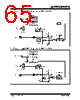
69 / 222 page  © 2006 Microchip Technology Inc. DS70119E-page 67 dsPIC30F6010 11.0 TIMER4/5 MODULE This section describes the second 32-bit General Purpose Timer module (Timer4/5) and associated operational modes. Figure 11-1 depicts the simplified block diagram of the 32-bit Timer4/5 Module. Figure 11-2 and Figure 11-3 show Timer4/5 configured as two independent 16-bit timers, Timer4 and Timer5, respectively. The Timer4/5 module is similar in operation to the Timer 2/3 module. However, there are some differences, which are listed below: • The Timer4/5 module does not support the ADC Event Trigger feature • Timer4/5 can not be utilized by other peripheral modules such as Input Capture and Output Compare The operating modes of the Timer4/5 module are determined by setting the appropriate bit(s) in the 16-bit T4CON and T5CON SFRs. For 32-bit timer/counter operation, Timer4 is the least significant word and Timer5 is the most significant word of the 32-bit timer. FIGURE 11-1: 32-BIT TIMER4/5 BLOCK DIAGRAM Note: This data sheet summarizes features of this group of dsPIC30F devices and is not intended to be a complete reference source. For more information on the CPU, peripherals, register descriptions and general device functionality, refer to the “dsPIC30F Family Reference Manual” (DS70046). Note: Timer4 is a ‘Type B’ timer and Timer5 is a ‘Type C’ timer. Please refer to the appro- priate timer type in Section 24.0 “Electri- cal Characteristics” of this document. Note: For 32-bit timer operation, T5CON control bits are ignored. Only T4CON control bits are used for setup and control. Timer4 clock and gate inputs are utilized for the 32-bit timer module, but an interrupt is generated with the Timer5 interrupt flag (T5IF) and the interrupt is enabled with the Timer5 Interrupt Enable bit (T5IE). TMR5 TMR4 T5IF Equal Comparator x 32 PR5 PR4 Reset LSB MSB Event Flag Note: Timer Configuration bit T32, T4CON(<3>) must be set to ‘1’ for a 32-bit timer/counter operation. All control bits are respective to the T4CON register. Data Bus<15:0> TMR5HLD Read TMR4 Write TMR4 16 16 16 Q QD CK TGATE(T4CON<6>) (T4CON<6>) TGATE 0 1 TON TCKPS<1:0> Prescaler 1, 8, 64, 256 2 TCY 1 x 0 1 0 0 Gate T4CK Sync Sync |
|
Ligação URL |
| ALLDATASHEET é útil para você? [ DONATE ] |
Sobre Alldatasheet | Publicidade | Contato conosco | Privacy Policy | Link para a ficha técnica | roca de Link | Lista de Fabricantes All Rights Reserved©Alldatasheet.com |
| Russian : Alldatasheetru.com | Korean : Alldatasheet.co.kr | Spanish : Alldatasheet.es | French : Alldatasheet.fr | Italian : Alldatasheetit.com Portuguese : Alldatasheetpt.com | Polish : Alldatasheet.pl | Vietnamese : Alldatasheet.vn Indian : Alldatasheet.in | Mexican : Alldatasheet.com.mx | British : Alldatasheet.co.uk | New Zealand : Alldatasheet.co.nz |
|
Family Site : ic2ic.com |
icmetro.com |
 Portuguese ▼
 English
 Chinese
 German
 Japanese
 Russian
 Korean
 Spanish
 French
 Italian
 Portuguese
 Polish
 Vietnamese
 Indian
 Mexican
 British
 New Zealand