|
Os motores de busca de Datasheet de Componentes eletrônicos |
|
|
Os motores de busca de Datasheet de Componentes eletrônicos |
|
DSPIC30F6010 Folha de dados(PDF) 66 Page - Microchip Technology |
|
|
|||||||||||||||||||||||||||||
DSPIC30F6010 Folha de dados(HTML) 66 Page - Microchip Technology |
|
|
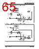
66 / 222 page  dsPIC30F6010 DS70119E-page 64 © 2006 Microchip Technology Inc. 10.1 Timer Gate Operation The 32-bit timer can be placed in the Gated Time Accu- mulation mode. This mode allows the internal TCY to increment the respective timer when the gate input sig- nal (T2CK pin) is asserted high. Control bit TGATE (T2CON<6>) must be set to enable this mode. When in this mode, Timer2 is the originating clock source. The TGATE setting is ignored for Timer3. The timer must be enabled (TON = 1) and the timer clock source set to internal (TCS = 0). The falling edge of the external signal terminates the count operation, but does not reset the timer. The user must reset the timer in order to start counting from zero. 10.2 ADC Event Trigger When a match occurs between the 32-bit timer (TMR3/ TMR2) and the 32-bit combined period register (PR3/ PR2), a special ADC trigger event signal is generated by Timer3. 10.3 Timer Prescaler The input clock (FOSC/4 or external clock) to the timer has a prescale option of 1:1, 1:8, 1:64, and 1:256 selected by control bits TCKPS<1:0> (T2CON<5:4> and T3CON<5:4>). For the 32-bit timer operation, the originating clock source is Timer2. The prescaler oper- ation for Timer3 is not applicable in this mode. The prescaler counter is cleared when any of the following occurs: • a write to the TMR2/TMR3 register • clearing either of the TON (T2CON<15> or T3CON<15>) bits to ‘0’ • device Reset such as POR and BOR However, if the timer is disabled (TON = 0), then the Timer 2 prescaler cannot be reset, since the prescaler clock is halted. TMR2/TMR3 is not cleared when T2CON/T3CON is written. 10.4 Timer Operation During Sleep Mode During CPU Sleep mode, the timer will not operate, because the internal clocks are disabled. 10.5 Timer Interrupt The 32-bit timer module can generate an interrupt on period match, or on the falling edge of the external gate signal. When the 32-bit timer count matches the respective 32-bit period register, or the falling edge of the external “gate” signal is detected, the T3IF bit (IFS0<7>) is asserted and an interrupt will be gener- ated if enabled. In this mode, the T3IF interrupt flag is used as the source of the interrupt. The T3IF bit must be cleared in software. Enabling an interrupt is accomplished via the respective Timer Interrupt Enable bit, T3IE (IEC0<7>). |
|
Ligação URL |
| ALLDATASHEET é útil para você? [ DONATE ] |
Sobre Alldatasheet | Publicidade | Contato conosco | Privacy Policy | Link para a ficha técnica | roca de Link | Lista de Fabricantes All Rights Reserved©Alldatasheet.com |
| Russian : Alldatasheetru.com | Korean : Alldatasheet.co.kr | Spanish : Alldatasheet.es | French : Alldatasheet.fr | Italian : Alldatasheetit.com Portuguese : Alldatasheetpt.com | Polish : Alldatasheet.pl | Vietnamese : Alldatasheet.vn Indian : Alldatasheet.in | Mexican : Alldatasheet.com.mx | British : Alldatasheet.co.uk | New Zealand : Alldatasheet.co.nz |
|
Family Site : ic2ic.com |
icmetro.com |
 Portuguese ▼
 English
 Chinese
 German
 Japanese
 Russian
 Korean
 Spanish
 French
 Italian
 Portuguese
 Polish
 Vietnamese
 Indian
 Mexican
 British
 New Zealand