|
Os motores de busca de Datasheet de Componentes eletrônicos |
|
|
Os motores de busca de Datasheet de Componentes eletrônicos |
|
DSPIC30F6010 Folha de dados(PDF) 74 Page - Microchip Technology |
|
|
|||||||||||||||||||||||||||||
DSPIC30F6010 Folha de dados(HTML) 74 Page - Microchip Technology |
|
|
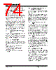
74 / 222 page  dsPIC30F6010 DS70119E-page 72 © 2006 Microchip Technology Inc. 12.1.2 CAPTURE BUFFER OPERATION Each capture channel has an associated FIFO buffer, which is four 16-bit words deep. There are two status flags, which provide status on the FIFO buffer: • ICBFNE – Input Capture Buffer Not Empty • ICOV – Input Capture Overflow The ICBFNE will be set on the first input capture event and remain set until all capture events have been read from the FIFO. As each word is read from the FIFO, the remaining words are advanced by one position within the buffer. In the event that the FIFO is full with four capture events and a fifth capture event occurs prior to a read of the FIFO, an overflow condition will occur and the ICOV bit will be set to a logic ‘1’. The fifth capture event is lost and is not stored in the FIFO. No additional events will be captured until all four events have been read from the buffer. If a FIFO read is performed after the last read and no new capture event has been received, the read will yield indeterminate results. 12.1.3 TIMER2 AND TIMER3 SELECTION MODE Each capture channel can select between one of two timers for the time base, Timer2 or Timer3. Selection of the timer resource is accomplished through SFR bit ICTMR (ICxCON<7>). Timer3 is the default timer resource available for the input capture module. 12.1.4 HALL SENSOR MODE When the input capture module is set for capture on every edge, rising and falling, ICM<2:0> = 001, the fol- lowing operations are performed by the input capture logic: • The input capture interrupt flag is set on every edge, rising and falling. • The interrupt on Capture mode setting bits, ICI<1:0>, is ignored, since every capture generates an interrupt. • A capture overflow condition is not generated in this mode. 12.2 Input Capture Operation During Sleep and Idle Modes An input capture event will generate a device wake-up or interrupt, if enabled, if the device is in CPU Idle or Sleep mode. Independent of the timer being enabled, the input capture module will wake-up from the CPU Sleep or Idle mode when a capture event occurs, if ICM<2:0> = 111 and the Interrupt Enable bit is asserted. The same wake-up can generate an interrupt, if the conditions for processing the interrupt have been satisfied. The wake-up feature is useful as a method of adding extra external pin interrupts. 12.2.1 INPUT CAPTURE IN CPU SLEEP MODE CPU Sleep mode allows input capture module opera- tion with reduced functionality. In the CPU Sleep mode, the ICI<1:0> bits are not applicable, and the input capture module can only function as an external interrupt source. The capture module must be configured for interrupt only on the rising edge (ICM<2:0> = 111), in order for the input capture module to be used while the device is in Sleep mode. The prescale settings of 4:1 or 16:1 are not applicable in this mode. 12.2.2 INPUT CAPTURE IN CPU IDLE MODE CPU Idle mode allows input capture module operation with full functionality. In the CPU Idle mode, the Inter- rupt mode selected by the ICI<1:0> bits are applicable, as well as the 4:1 and 16:1 capture prescale settings, which are defined by control bits ICM<2:0>. This mode requires the selected timer to be enabled. Moreover, the ICSIDL bit must be asserted to a logic ‘0’. If the input capture module is defined as ICM<2:0> = 111 in CPU Idle mode, the input capture pin will serve only as an external interrupt pin. 12.3 Input Capture Interrupts The input capture channels have the ability to generate an interrupt, based upon the selected number of cap- ture events. The selection number is set by control bits ICI<1:0> (ICxCON<6:5>). Each channel provides an interrupt flag (ICxIF) bit. The respective capture channel interrupt flag is located in the corresponding IFSx Status register. Enabling an interrupt is accomplished via the respec- tive capture channel interrupt enable (ICxIE) bit. The Capture Interrupt Enable bit is located in the corresponding IEC Control register. |
|
Ligação URL |
| ALLDATASHEET é útil para você? [ DONATE ] |
Sobre Alldatasheet | Publicidade | Contato conosco | Privacy Policy | Link para a ficha técnica | roca de Link | Lista de Fabricantes All Rights Reserved©Alldatasheet.com |
| Russian : Alldatasheetru.com | Korean : Alldatasheet.co.kr | Spanish : Alldatasheet.es | French : Alldatasheet.fr | Italian : Alldatasheetit.com Portuguese : Alldatasheetpt.com | Polish : Alldatasheet.pl | Vietnamese : Alldatasheet.vn Indian : Alldatasheet.in | Mexican : Alldatasheet.com.mx | British : Alldatasheet.co.uk | New Zealand : Alldatasheet.co.nz |
|
Family Site : ic2ic.com |
icmetro.com |
 Portuguese ▼
 English
 Chinese
 German
 Japanese
 Russian
 Korean
 Spanish
 French
 Italian
 Portuguese
 Polish
 Vietnamese
 Indian
 Mexican
 British
 New Zealand