|
Os motores de busca de Datasheet de Componentes eletrônicos |
|
|
Os motores de busca de Datasheet de Componentes eletrônicos |
|
DSPIC30F6010 Folha de dados(PDF) 79 Page - Microchip Technology |
|
|
|||||||||||||||||||||||||||||
DSPIC30F6010 Folha de dados(HTML) 79 Page - Microchip Technology |
|
|
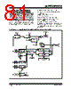
79 / 222 page  © 2006 Microchip Technology Inc. DS70119E-page 77 dsPIC30F6010 13.4.2 PWM PERIOD The PWM period is specified by writing to the PRx reg- ister. The PWM period can be calculated using Equation 13-1. EQUATION 13-1: PWM PERIOD PWM frequency is defined as 1/[PWM period]. When the selected TMRx is equal to its respective period register, PRx, the following four events occur on the next increment cycle: • TMRx is cleared. • The OCx pin is set. - Exception 1: If PWM duty cycle is 0x0000, the OCx pin will remain low. - Exception 2: If duty cycle is greater than PRx, the pin will remain high. • The PWM duty cycle is latched from OCxRS into OCxR. • The corresponding timer interrupt flag is set. See Figure 13-1 for key PWM period comparisons. Timer3 is referred to in the figure for clarity. FIGURE 13-1: PWM OUTPUT TIMING 13.5 Output Compare Operation During CPU Sleep Mode When the CPU enters the Sleep mode, all internal clocks are stopped. Therefore, when the CPU enters the Sleep state, the output compare channel will drive the pin to the active state that was observed prior to entering the CPU Sleep state. For example, if the pin was high when the CPU entered the Sleep state, the pin will remain high. Like- wise, if the pin was low when the CPU entered the Sleep state, the pin will remain low. In either case, the output compare module will resume operation when the device wakes up. 13.6 Output Compare Operation During CPU Idle Mode When the CPU enters the Idle mode, the output compare module can operate with full functionality. The output compare channel will operate during the CPU Idle mode if the OCSIDL bit (OCxCON<13>) is at logic 0 and the selected time base (Timer2 or Timer3) is enabled and the TSIDL bit of the selected timer is set to logic 0. 13.7 Output Compare Interrupts The output compare channels have the ability to gener- ate an interrupt on a compare match, for whichever match mode has been selected. For all modes except the PWM mode, when a compare event occurs, the respective interrupt flag (OCxIF) is asserted and an interrupt will be generated, if enabled. The OCxIF bit is located in the corresponding IFS Status register, and must be cleared in software. The interrupt is enabled via the respective compare inter- rupt enable (OCxIE) bit, located in the corresponding IEC Control register. For the PWM mode, when an event occurs, the respec- tive timer interrupt flag (T2IF or T3IF) is asserted and an interrupt will be generated, if enabled. The IF bit is located in the IFS0 Status register, and must be cleared in software. The interrupt is enabled via the respective Timer Interrupt Enable bit (T2IE or T3IE), located in the IEC0 Control register. The output compare interrupt flag is never set during the PWM mode of operation. PWM period = [(PRx) + 1] • 4 • TOSC • (TMRx prescale value) Period Duty Cycle TMR3 = Duty Cycle (OCxR) TMR3 = Duty Cycle (OCxR) TMR3 = PR3 T3IF = 1 (Interrupt Flag) OCxR = OCxRS TMR3 = PR3 (Interrupt Flag) OCxR = OCxRS T3IF = 1 |
|
Ligação URL |
| ALLDATASHEET é útil para você? [ DONATE ] |
Sobre Alldatasheet | Publicidade | Contato conosco | Privacy Policy | Link para a ficha técnica | roca de Link | Lista de Fabricantes All Rights Reserved©Alldatasheet.com |
| Russian : Alldatasheetru.com | Korean : Alldatasheet.co.kr | Spanish : Alldatasheet.es | French : Alldatasheet.fr | Italian : Alldatasheetit.com Portuguese : Alldatasheetpt.com | Polish : Alldatasheet.pl | Vietnamese : Alldatasheet.vn Indian : Alldatasheet.in | Mexican : Alldatasheet.com.mx | British : Alldatasheet.co.uk | New Zealand : Alldatasheet.co.nz |
|
Family Site : ic2ic.com |
icmetro.com |
 Portuguese ▼
 English
 Chinese
 German
 Japanese
 Russian
 Korean
 Spanish
 French
 Italian
 Portuguese
 Polish
 Vietnamese
 Indian
 Mexican
 British
 New Zealand