|
Os motores de busca de Datasheet de Componentes eletrônicos |
|
|
Os motores de busca de Datasheet de Componentes eletrônicos |
|
CC1010-RTY1 Folha de dados(PDF) 19 Page - Texas Instruments |
|
|
|
|||||||||||||||||||||||||||||
CC1010-RTY1 Folha de dados(HTML) 19 Page - Texas Instruments |
|
|
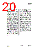
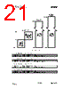
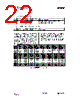
19 / 152 page  CC1010 SWRS047 Page 19 of 152 15. 8051 Core 15.1 General description The CC1010 microcontroller core is based on the industry-standard 8051 architecture. The MCU core is 8-bit, with program and data memory located in separate memory spaces (Harvard architecture). The internal registers are organised as four banks of 8 registers each. The instruction set supports direct, indirect and register addressing modes. Program memory can be addressed using indexed addressing. The core registers are comprised of an accumulator, a stack pointer and dual data pointer registers in addition to the general registers. Data memory is split into internal and external RAM. The name "external RAM" is in fact misleading since in the case of the CC1010 all the RAM is internal to the chip. The difference between external and internal is that external RAM can only be accessed by a few instructions. Therefore, frequently-accessed variables as well as the stack should be kept in internal RAM. The various peripherals are controlled through Special Function Registers (SFRs) located in the internal RAM space. The 8051 core is instruction set compatible with the industry standard 8051. It also has one additional instruction, TRAP, to enable advanced in-circuit- debugging features. This is described on page 44. The instruction cycle time is 4 clock cycles, which typically gives a 2.5X average reduction in instruction execution time over the original Intel 8051. Peripheral units, including general purpose I/O, 2 standard 8051 timers, 2 extra timers with PWM functionality, a watchdog timer, a real-time clock, an SPI master interface, hardware DES encryption, a true random bit generator and ADC are all described from page 47 and out. Dual data pointers are available for faster data transfer. 15.2 Reset CC1010 must be reset at start-up. There are several sources for reset in CC1010 : • External reset pin, RESET . Applying a low signal to this pin at any time will reset almost all registers in CC1010. Exceptions can be found in Table 41 on page 144. The input is asynchronous and is synchronised internally, so that the reset can be released independent of the timing of the active clock signal. If the main crystal oscillator is inactive, the reset input should be held long enough for the oscillator to start up and stabilize. See Electrical Specifications page 7 for oscillator start-up timing. • Power On Reset (POR). The internal POR module can generate reset upon power-up. Special requirements for power consumption or power supply voltage may require an external POR module, as described in the Power On Reset (Brown-Out Detection) section at page 62. • Brown-out detection reset. The POR will also detect low supply voltage and generate a reset. • Watchdog timer reset. The watchdog timer can generate a reset, as described in the section on page 63. • ADC reset. The ADC module can be programmed to generate a reset signal if its inputs exceed a programmed threshold. See the ADC section on page 79 for details. The POR and ADC reset signals will be held for 1024 clock periods after the signal is released. This will ensure a safe clock start-up if the crystal oscillator is currently not running. |
|
Ligação URL |
| ALLDATASHEET é útil para você? [ DONATE ] |
Sobre Alldatasheet | Publicidade | Contato conosco | Privacy Policy | Link para a ficha técnica | roca de Link | Lista de Fabricantes All Rights Reserved©Alldatasheet.com |
| Russian : Alldatasheetru.com | Korean : Alldatasheet.co.kr | Spanish : Alldatasheet.es | French : Alldatasheet.fr | Italian : Alldatasheetit.com Portuguese : Alldatasheetpt.com | Polish : Alldatasheet.pl | Vietnamese : Alldatasheet.vn Indian : Alldatasheet.in | Mexican : Alldatasheet.com.mx | British : Alldatasheet.co.uk | New Zealand : Alldatasheet.co.nz |
|
Family Site : ic2ic.com |
icmetro.com |
 Portuguese ▼
 English
 Chinese
 German
 Japanese
 Russian
 Korean
 Spanish
 French
 Italian
 Portuguese
 Polish
 Vietnamese
 Indian
 Mexican
 British
 New Zealand