|
Os motores de busca de Datasheet de Componentes eletrônicos |
|
|
Os motores de busca de Datasheet de Componentes eletrônicos |
|
PIC12F508 Folha de dados(PDF) 49 Page - Microchip Technology |
|
|
|||||||||||||||||||||||||||||
PIC12F508 Folha de dados(HTML) 49 Page - Microchip Technology |
|
|
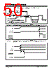
49 / 110 page  © 2009 Microchip Technology Inc. DS41236E-page 49 PIC12F508/509/16F505 7.3.1 MCLR ENABLE This Configuration bit, when unprogrammed (left in the ‘1’ state), enables the external MCLR function. When programmed, the MCLR function is tied to the internal VDD and the pin is assigned to be an input only. See Figure 7-6. FIGURE 7-6: MCLR SELECT 7.4 Power-on Reset (POR) The PIC12F508/509/16F505 devices incorporate an on-chip Power-on Reset (POR) circuitry, which provides an internal chip Reset for most power-up situations. The on-chip POR circuit holds the chip in Reset until VDD has reached a high enough level for proper operation. To take advantage of the internal POR, program the (GP3/RB3)/MCLR/VPP pin as MCLR and tie through a resistor to VDD, or program the pin as (GP3/RB3). An internal weak pull-up resistor is implemented using a transistor (refer to Table 10-2 for the pull-up resistor ranges). This will eliminate external RC components usually needed to create a Power-on Reset. A maximum rise time for VDD is specified. See Section 10.0 “Electrical Characteristics” for details. When the devices start normal operation (exit the Reset condition), device operating parameters (voltage, frequency, temperature,...) must be met to ensure operation. If these conditions are not met, the devices must be held in Reset until the operating parameters are met. A simplified block diagram of the on-chip Power-on Reset circuit is shown in Figure 7-7. The Power-on Reset circuit and the Device Reset Timer (see Section 7.5 “Device Reset Timer (DRT)”) circuit are closely related. On power-up, the Reset latch is set and the DRT is reset. The DRT timer begins counting once it detects MCLR to be high. After the time-out period, which is typically 18 ms, it will reset the Reset latch and thus end the on-chip Reset signal. A power-up example where MCLR is held low is shown in Figure 7-8. VDD is allowed to rise and stabilize before bringing MCLR high. The chip will actually come out of Reset TDRT msec after MCLR goes high. In Figure 7-9, the on-chip Power-on Reset feature is being used (MCLR and VDD are tied together or the pin is programmed to be (GP3/RB3). The VDD is stable before the start-up timer times out and there is no prob- lem in getting a proper Reset. However, Figure 7-10 depicts a problem situation where VDD rises too slowly. The time between when the DRT senses that MCLR is high and when MCLR and VDD actually reach their full value, is too long. In this situation, when the start-up timer times out, VDD has not reached the VDD (min) value and the chip may not function correctly. For such situations, we recommend that external RC circuits be used to achieve longer POR delay times (Figure 7-9). For additional information, refer to Application Notes AN522 “Power-Up Considerations” (DS00522) and AN607 “Power-up Trouble Shooting” (DS00607). (GP3/RB3)/MCLR/VPP MCLRE Internal MCLR GPWU/RBWU Note: When the devices start normal operation (exit the Reset condition), device operat- ing parameters (voltage, frequency, tem- perature, etc.) must be met to ensure operation. If these conditions are not met, the device must be held in Reset until the operating conditions are met. |
|
Ligação URL |
| ALLDATASHEET é útil para você? [ DONATE ] |
Sobre Alldatasheet | Publicidade | Contato conosco | Privacy Policy | Link para a ficha técnica | roca de Link | Lista de Fabricantes All Rights Reserved©Alldatasheet.com |
| Russian : Alldatasheetru.com | Korean : Alldatasheet.co.kr | Spanish : Alldatasheet.es | French : Alldatasheet.fr | Italian : Alldatasheetit.com Portuguese : Alldatasheetpt.com | Polish : Alldatasheet.pl | Vietnamese : Alldatasheet.vn Indian : Alldatasheet.in | Mexican : Alldatasheet.com.mx | British : Alldatasheet.co.uk | New Zealand : Alldatasheet.co.nz |
|
Family Site : ic2ic.com |
icmetro.com |
 Portuguese ▼
 English
 Chinese
 German
 Japanese
 Russian
 Korean
 Spanish
 French
 Italian
 Portuguese
 Polish
 Vietnamese
 Indian
 Mexican
 British
 New Zealand