|
Os motores de busca de Datasheet de Componentes eletrônicos |
|
|
Os motores de busca de Datasheet de Componentes eletrônicos |
|
PIC12F508 Folha de dados(PDF) 35 Page - Microchip Technology |
|
|
|||||||||||||||||||||||||||||
PIC12F508 Folha de dados(HTML) 35 Page - Microchip Technology |
|
|
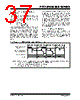
35 / 110 page  © 2009 Microchip Technology Inc. DS41236E-page 35 PIC12F508/509/16F505 6.0 TIMER0 MODULE AND TMR0 REGISTER The Timer0 module has the following features: • 8-bit timer/counter register, TMR0 • Readable and writable • 8-bit software programmable prescaler • Internal or external clock select: - Edge select for external clock Figure 6-1 is a simplified block diagram of the Timer0 module. Timer mode is selected by clearing the T0CS bit (OPTION<5>). In Timer mode, the Timer0 module will increment every instruction cycle (without prescaler). If TMR0 register is written, the increment is inhibited for the following two cycles (Figure 6-2 and Figure 6-3). The user can work around this by writing an adjusted value to the TMR0 register. Counter mode is selected by setting the T0CS bit (OPTION<5>). In this mode, Timer0 will increment either on every rising or falling edge of pin T0CKI. The T0SE bit (OPTION<4>) determines the source edge. Clearing the T0SE bit selects the rising edge. Restric- tions on the external clock input are discussed in detail in Section 6.1 “Using Timer0 with an External Clock”. The prescaler may be used by either the Timer0 module or the Watchdog Timer, but not both. The prescaler assignment is controlled in software by the control bit, PSA (OPTION<3>). Clearing the PSA bit will assign the prescaler to Timer0. The prescaler is not readable or writable. When the prescaler is assigned to the Timer0 module, prescale values of 1:2, 1:4,..., 1:256 are selectable. Section 6.2 “Prescaler” details the operation of the prescaler. A summary of registers associated with the Timer0 module is found in Table 6-1. FIGURE 6-1: TIMER0 BLOCK DIAGRAM FIGURE 6-2: TIMER0 TIMING: INTERNAL CLOCK/NO PRESCALE Note 1: Bits T0CS, T0SE, PSA, PS2, PS1 and PS0 are located in the OPTION register. 2: The prescaler is shared with the Watchdog Timer (Figure 6-5). 0 1 1 0 T0CS(1) FOSC/4 Programmable Prescaler(2) Sync with Internal Clocks TMR0 Reg PSOUT (2 TCY delay) PSOUT Data Bus 8 PSA(1) PS2, PS1, PS0(1) 3 Sync T0SE (GP2/RC5)/T0CKI Pin PC – 1 Q1 Q2 Q3 Q4 Q1 Q2 Q3 Q4 Q1 Q2 Q3 Q4 Q1 Q2 Q3 Q4 Q1 Q2 Q3 Q4 Q1 Q2 Q3 Q4 Q1 Q2 Q3 Q4 Q1 Q2 Q3 Q4 Instruction Fetch Timer0 PC PC + 1 PC + 2 PC + 3 PC + 4 PC + 6 T0 T0 + 1 T0 + 2 NT0 NT0 + 1 NT0 + 2 MOVWF TMR0 MOVF TMR0,W MOVF TMR0,W MOVF TMR0,W MOVF TMR0,W MOVF TMR0,W Write TMR0 executed Read TMR0 reads NT0 Read TMR0 reads NT0 Read TMR0 reads NT0 Read TMR0 reads NT0 + 1 Read TMR0 reads NT0 + 2 Instruction Executed PC + 5 PC (Program Counter) |
|
Ligação URL |
| ALLDATASHEET é útil para você? [ DONATE ] |
Sobre Alldatasheet | Publicidade | Contato conosco | Privacy Policy | Link para a ficha técnica | roca de Link | Lista de Fabricantes All Rights Reserved©Alldatasheet.com |
| Russian : Alldatasheetru.com | Korean : Alldatasheet.co.kr | Spanish : Alldatasheet.es | French : Alldatasheet.fr | Italian : Alldatasheetit.com Portuguese : Alldatasheetpt.com | Polish : Alldatasheet.pl | Vietnamese : Alldatasheet.vn Indian : Alldatasheet.in | Mexican : Alldatasheet.com.mx | British : Alldatasheet.co.uk | New Zealand : Alldatasheet.co.nz |
|
Family Site : ic2ic.com |
icmetro.com |
 Portuguese ▼
 English
 Chinese
 German
 Japanese
 Russian
 Korean
 Spanish
 French
 Italian
 Portuguese
 Polish
 Vietnamese
 Indian
 Mexican
 British
 New Zealand