|
Os motores de busca de Datasheet de Componentes eletrônicos |
|
|
Os motores de busca de Datasheet de Componentes eletrônicos |
|
BMP280 Folha de dados(PDF) 28 Page - Bosch Sensortec GmbH |
|
|
|||||||||||||||||||||||||||||
BMP280 Folha de dados(HTML) 28 Page - Bosch Sensortec GmbH |
|
|
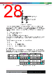
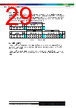
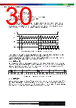
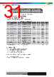
28 / 49 page  Bosch Sensortec | BMP280 Data sheet 28 | 49 Modifications reserved | Data subject to change without notice Document number: BST-BMP280-DS001-26 Revision_1.26_102021 GND VDDIO output driver (only for SDI) SDI /SCL high-z level shifter GND Figure 6: SDI/SCK ESD drawing The 7-bit device address is 111011x. The 6 MSB bits are fixed. The last bit is changeable by SDO value and can be changed during operation. Connecting SDO to GND results in slave address 1110110 (0x76); connection it to VDDIO results in slave address 1110111 (0x77), which is the same as BMP180’s I²C address. The SDO pin cannot be left floating; if left floating, the I²C address will be undefined. The I²C interface uses the following pins: • SCK: serial clock (SCL) • SDI: data (SDA) • SDO: Slave address LSB (GND = ‘0’, VDDIO = ‘1’) CSB must be connected to VDDIO to select I²C interface. SDI is bi-directional with open drain to GND: it must be externally connected to VDDIO via a pull up resistor. Refer to chapter 6 for connection instructions. The following abbreviations will be used in the I²C protocol figures: • S Start • P Stop • ACKS Acknowledge by slave • ACKM Acknowledge by master • NACKM Not acknowledge by master 5.2.1 I²C write Writing is done by sending the slave address in write mode (RW = ‘0’), resulting in slave address 111011X0 (‘X’ is determined by state of SDO pin. Then the master sends pairs of register addresses and register data. The transaction is ended by a stop condition. This is depicted in Figure 7. Start RW ACKS ACKS ACKS 1 1 1 0 1 1 X 0 1 0 1 0 0 0 0 0 bit7 bit6 bit5 bit4 bit3 bit2 bit1 bit0 … ACKS ACKS Stop … 1 0 1 0 0 0 0 1 bit7 bit6 bit5 bit4 bit3 bit2 bit1 bit0 Register data - address A0h Register address (A0h) Register address (A1h) S Slave Address Control byte Data byte Control byte Data byte P Register data - address A1h Figure 7: I²C multiple byte write (not auto-incremented) |
|
Ligação URL |
| ALLDATASHEET é útil para você? [ DONATE ] |
Sobre Alldatasheet | Publicidade | Contato conosco | Privacy Policy | Link para a ficha técnica | roca de Link | Lista de Fabricantes All Rights Reserved©Alldatasheet.com |
| Russian : Alldatasheetru.com | Korean : Alldatasheet.co.kr | Spanish : Alldatasheet.es | French : Alldatasheet.fr | Italian : Alldatasheetit.com Portuguese : Alldatasheetpt.com | Polish : Alldatasheet.pl | Vietnamese : Alldatasheet.vn Indian : Alldatasheet.in | Mexican : Alldatasheet.com.mx | British : Alldatasheet.co.uk | New Zealand : Alldatasheet.co.nz |
|
Family Site : ic2ic.com |
icmetro.com |
 Portuguese ▼
 English
 Chinese
 German
 Japanese
 Russian
 Korean
 Spanish
 French
 Italian
 Portuguese
 Polish
 Vietnamese
 Indian
 Mexican
 British
 New Zealand