|
Os motores de busca de Datasheet de Componentes eletrônicos |
|
|
Os motores de busca de Datasheet de Componentes eletrônicos |
|
BMP280 Folha de dados(PDF) 16 Page - Bosch Sensortec GmbH |
|
|
|||||||||||||||||||||||||||||
BMP280 Folha de dados(HTML) 16 Page - Bosch Sensortec GmbH |
|
|
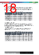
16 / 49 page  Bosch Sensortec | BMP280 Data sheet 16 | 49 Modifications reserved | Data subject to change without notice Document number: BST-BMP280-DS001-26 Revision_1.26_102021 selected again. This is similar to BMP180 operation. Forced mode is recommended for applications which require low sampling rate or host-based synchronization. time IDDSL IDDSB IDDP IDDT POR Mode[1:0] = 01 Data readout osrs_t osrs_p Write settings Mode[1:0] = 01 Figure 3: Forced mode timing diagram 3.6.3 Normal mode Normal mode 16ontinuously cycles between an (active) measurement period and an (inactive) standby period, whose time is defined by tstandby. The current in the standby period (IDDSB) is slightly higher than in sleep mode. After setting the mode,measurement and filter options, the last measurement results can be obtained from the data registers without the need of further write accesses. Normal mode is recommended when using the IIR filter, and useful for applications in which short-term disturbances (e.g. blowing into the sensor) should be filtered. time IDDSL IDDSB IDDP IDDT POR Mode[1:0] = 11 Data readout when needed osrs_t osrs_p Write settings tstandby Figure 4: Normal mode timing diagram The standby time is determined by the contents of the t_sb[2:0] bits in control register 0xF5 according to the table below: |
|
Ligação URL |
| ALLDATASHEET é útil para você? [ DONATE ] |
Sobre Alldatasheet | Publicidade | Contato conosco | Privacy Policy | Link para a ficha técnica | roca de Link | Lista de Fabricantes All Rights Reserved©Alldatasheet.com |
| Russian : Alldatasheetru.com | Korean : Alldatasheet.co.kr | Spanish : Alldatasheet.es | French : Alldatasheet.fr | Italian : Alldatasheetit.com Portuguese : Alldatasheetpt.com | Polish : Alldatasheet.pl | Vietnamese : Alldatasheet.vn Indian : Alldatasheet.in | Mexican : Alldatasheet.com.mx | British : Alldatasheet.co.uk | New Zealand : Alldatasheet.co.nz |
|
Family Site : ic2ic.com |
icmetro.com |
 Portuguese ▼
 English
 Chinese
 German
 Japanese
 Russian
 Korean
 Spanish
 French
 Italian
 Portuguese
 Polish
 Vietnamese
 Indian
 Mexican
 British
 New Zealand