|
Os motores de busca de Datasheet de Componentes eletrônicos |
|
|
Os motores de busca de Datasheet de Componentes eletrônicos |
|
BMP280 Folha de dados(PDF) 27 Page - Bosch Sensortec GmbH |
|
|
|||||||||||||||||||||||||||||
BMP280 Folha de dados(HTML) 27 Page - Bosch Sensortec GmbH |
|
|
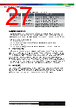
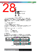
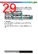
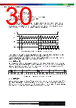
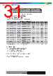
27 / 49 page  Bosch Sensortec | BMP280 Data sheet 27 | 49 Modifications reserved | Data subject to change without notice Document number: BST-BMP280-DS001-26 Revision_1.26_102021 Table 25: Register 0xFA … 0xFC “temp” Register 0xFA- 0xFC “press” Name Description 0xFA temp_msb[7:0] Contains the MSB part ut[19:12] of the raw temperature measurement output data. 0xFB temp_lsb[7:0] Contains the LSB part ut[11:4] of the raw temperature measurement output data. 0xFC (bit 7, 6, 5, 4) temp_xlsb[3:0] Contains the XLSB part ut[3:0] of the raw temperature measurement output data. Contents depend on pressure resolution, see Table 4. 5. Digital interfaces The BMP280 supports the I²C and SPI digital interfaces; it acts as a slave for both protocols. The I²C interface supports the Standard, Fast and High Speed modes. The SPI interface supports both SPI mode ‘00’ (CPOL = CPHA = ‘0’) and mode ‘11’ (CPOL = CPHA = ‘1’) in 4-wire and 3-wire configuration. The following transactions are supported: • Single byte write • multiple byte write (using pairs of register addresses and register data) • single byte read • multiple byte read (using a single register address which is auto-incremented) 5.1 Interface selection Interface selection is done automatically based on CSB (chip select) status. If CSB is connected to VDDIO, the I²C interface is active. If CSB is pulled down, the SPI interface is activated. After CSB has been pulled down once (regardless of whether any clock cycle occurred), the I²C interface is disabled until the next power-on-reset. This is done in order to avoid inadvertently decoding SPI traffic to another slave as I²C data. Since power-on-reset is only executed when both VDD and VDDIO are established, there is no risk of incorrect protocol detection due to power-up sequence used. However, if I²C is to be used and CSB is not directly connected to VDDIO but rather through a programmable pin, it must be ensured that this pin already outputs the VDDIO level during power-on-reset of the device. If this is not the case, the device will be locked in SPI mode and not respond to I²C commands. 5.2 I²C Interface The I²C slave interface is compatible with Philips I²C Specification version 2.1. For detailed timings refer to Table 27. All modes (standard, fast, high speed) are supported. SDA and SCL are not pure open-drain. Both pads contain ESD protection diodes to VDDIO and GND. As the devices does not perform clock stretching, the SCL structure is a high-Z input without drain capability. |
|
Ligação URL |
| ALLDATASHEET é útil para você? [ DONATE ] |
Sobre Alldatasheet | Publicidade | Contato conosco | Privacy Policy | Link para a ficha técnica | roca de Link | Lista de Fabricantes All Rights Reserved©Alldatasheet.com |
| Russian : Alldatasheetru.com | Korean : Alldatasheet.co.kr | Spanish : Alldatasheet.es | French : Alldatasheet.fr | Italian : Alldatasheetit.com Portuguese : Alldatasheetpt.com | Polish : Alldatasheet.pl | Vietnamese : Alldatasheet.vn Indian : Alldatasheet.in | Mexican : Alldatasheet.com.mx | British : Alldatasheet.co.uk | New Zealand : Alldatasheet.co.nz |
|
Family Site : ic2ic.com |
icmetro.com |
 Portuguese ▼
 English
 Chinese
 German
 Japanese
 Russian
 Korean
 Spanish
 French
 Italian
 Portuguese
 Polish
 Vietnamese
 Indian
 Mexican
 British
 New Zealand