|
Os motores de busca de Datasheet de Componentes eletrônicos |
|
|
Os motores de busca de Datasheet de Componentes eletrônicos |
|
BMP280 Folha de dados(PDF) 20 Page - Bosch Sensortec GmbH |
|
|
|||||||||||||||||||||||||||||
BMP280 Folha de dados(HTML) 20 Page - Bosch Sensortec GmbH |
|
|
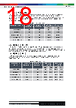
20 / 49 page  Bosch Sensortec | BMP280 Data sheet 20 | 49 Modifications reserved | Data subject to change without notice Document number: BST-BMP280-DS001-26 Revision_1.26_102021 3.9 Data readout To read out data after a conversion, it is strongly recommended to use a burst read and not address every register individually. This will prevent a possible mix-up of bytes belonging to different measurements and reduce interface traffic. Data readout is done by starting a burst read from 0xF7 to 0xFC. The data are read out in an unsigned 20-bit format both for pressure and for temperature. It is strongly recommended to use the BMP280 API, available from Bosch Sensortec, for readout and compensation. For details on memory map and interfaces, please consult chapters 3.12 and 5 respectively. The timing for data readout in forced mode should be done so that the maximum measurement times (see chapter 3.8.1) are respected. In normal mode, readout can be done at a speed similar to the expected data output rate (see chapter 3.8.2). After the values of ‘ut’ and ‘up’ have been read, the actual pressure and temperature need to be calculated using the compensation parameters stored in the device. The procedure is elaborated in chapter 3.11. 3.10 Data register shadowing In normal mode, measurement timing is not necessarily synchronized to readout. This means that new measurement results may become available while the user is reading the results from the previous measurement. In this case, shadowing is performed in order to guarantee data consistency. Shadowing will only work if all data registers are read in a single burst read. Therefore, the user must use burst reads if he does not synchronize data readout with the measurement cycle. Using several independent read commands may result in inconsistent data. If a new measurement is finished and the data registers are still being read, the new measurement results are transferred into shadow data registers. The content of shadow registers is transferred into data registers as soon as the user ends the burst read, even if not all data registers were read. Reading across several data registers can therefore only be guaranteed to be consistent within one measurement cycle if a single burst read command is used. The end of the burst read is marked by the rising edge of CSB pin in SPI case or by the recognition of a stop condition in I2C case. After the end of the burst read, all user data registers are updated at once. 3.11 Output compensation The BMP280 output consists of the ADC output values. However, each sensing element behaves differently, and actual pressure and temperature must be calculated using a set of calibration parameters. The recommended calculation in chapter 3.11.3 uses fixed point arithmetic. In high-level languages like Matlab™ or LabVIEW™, fixed-point code may not be well supported. In this case the floating-point code in appendix 8.1 can be used as an alternative. For 8-bit micro controllers, the variable size may be limited. In this case a simplified 32 bit integer code with reduced accuracy is given in appendix 8.2. 3.11.1 Computational requirements The table below shows the number of clock cycles needed for compensation calculations on a 32 bit Cortex-M3 micro controller with GCC optimization level –O2. This controller does not contain a floating point unit, so all floating-point calculations are emulated. Floating point is only recommended for PC applications where an FPU is present. |
|
Ligação URL |
| ALLDATASHEET é útil para você? [ DONATE ] |
Sobre Alldatasheet | Publicidade | Contato conosco | Privacy Policy | Link para a ficha técnica | roca de Link | Lista de Fabricantes All Rights Reserved©Alldatasheet.com |
| Russian : Alldatasheetru.com | Korean : Alldatasheet.co.kr | Spanish : Alldatasheet.es | French : Alldatasheet.fr | Italian : Alldatasheetit.com Portuguese : Alldatasheetpt.com | Polish : Alldatasheet.pl | Vietnamese : Alldatasheet.vn Indian : Alldatasheet.in | Mexican : Alldatasheet.com.mx | British : Alldatasheet.co.uk | New Zealand : Alldatasheet.co.nz |
|
Family Site : ic2ic.com |
icmetro.com |
 Portuguese ▼
 English
 Chinese
 German
 Japanese
 Russian
 Korean
 Spanish
 French
 Italian
 Portuguese
 Polish
 Vietnamese
 Indian
 Mexican
 British
 New Zealand