|
Os motores de busca de Datasheet de Componentes eletrônicos |
|
|
Os motores de busca de Datasheet de Componentes eletrônicos |
|
PIC16F5X Folha de dados(PDF) 27 Page - Microchip Technology |
|
|
|||||||||||||||||||||||||||||
PIC16F5X Folha de dados(HTML) 27 Page - Microchip Technology |
|
|
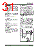
27 / 88 page  © 2007 Microchip Technology Inc. DS41213D-page 25 PIC16F5X 5.1 Power-on Reset (POR) The PIC16F5X family of devices incorporate on-chip Power-on Reset (POR) circuitry which provides an internal chip Reset for most power-up situations. To use this feature, the user merely ties the MCLR/VPP pin to VDD. A simplified block diagram of the on-chip Power-on Reset circuit is shown in Figure 5-1. The Power-on Reset circuit and the Device Reset Timer (Section 5.2) circuit are closely related. On power-up, the Reset latch is set and the DRT is reset. The DRT timer begins counting once it detects MCLR to be high. After the time-out period, which is typically 18 ms, it will reset the Reset latch and thus end the on- chip Reset signal. A power-up example where MCLR is not tied to VDD is shown in Figure 5-3. VDD is allowed to rise and stabilize before bringing MCLR high. The chip will actually come out of Reset TDRT msec after MCLR goes high. In Figure 5-4, the on-chip Power-on Reset feature is being used (MCLR and VDD are tied together). The VDD is stable before the start-up timer times out and there is no problem in getting a proper Reset. However, Figure 5-5 depicts a problem situation where VDD rises too slowly. The time between when the DRT senses a high on the MCLR/VPP pin and the MCLR/VPP pin (and VDD) actually reach their full value is too long. In this sit- uation, when the start-up timer times out, VDD has not reached the VDD (min) value and the chip is, therefore, not ensured to function correctly. For such situations, we recommend that external RC circuits be used to achieve longer POR delay times (Figure 5-2). For more information on the PIC16F5X POR, see Application Note AN522, “Power-Up Considerations” at www.microchip.com. FIGURE 5-2: EXTERNAL POWER-ON RESET CIRCUIT (FOR SLOW VDD POWER-UP) Note 1: When the device starts normal operation (exits the Reset condition), device operating parameters (voltage, fre- quency, temperature, etc.) must be met to ensure operation. If these conditions are not met, the device must be held in Reset until the operating conditions are met. 2: The POR is disabled when the device is in Sleep. C R1 R D MCLR PIC16F5X VDD VDD • External Power-on Reset circuit is required only if VDD power-up is too slow. The diode D helps discharge the capacitor quickly when VDD powers down. •R < 40 k Ω is recommended to make sure that voltage drop across R does not violate the device electrical specification. •R1 = 100 Ω to 1 kΩ will limit any current flowing into MCLR from external capacitor C in the event of MCLR pin breakdown due to Electrostatic Discharge (ESD) or Electrical Overstress (EOS). |
|
Ligação URL |
| ALLDATASHEET é útil para você? [ DONATE ] |
Sobre Alldatasheet | Publicidade | Contato conosco | Privacy Policy | Link para a ficha técnica | roca de Link | Lista de Fabricantes All Rights Reserved©Alldatasheet.com |
| Russian : Alldatasheetru.com | Korean : Alldatasheet.co.kr | Spanish : Alldatasheet.es | French : Alldatasheet.fr | Italian : Alldatasheetit.com Portuguese : Alldatasheetpt.com | Polish : Alldatasheet.pl | Vietnamese : Alldatasheet.vn Indian : Alldatasheet.in | Mexican : Alldatasheet.com.mx | British : Alldatasheet.co.uk | New Zealand : Alldatasheet.co.nz |
|
Family Site : ic2ic.com |
icmetro.com |
 Portuguese ▼
 English
 Chinese
 German
 Japanese
 Russian
 Korean
 Spanish
 French
 Italian
 Portuguese
 Polish
 Vietnamese
 Indian
 Mexican
 British
 New Zealand