|
Os motores de busca de Datasheet de Componentes eletrônicos |
|
|
Os motores de busca de Datasheet de Componentes eletrônicos |
|
ADP151 Folha de dados(PDF) 28 Page - Analog Devices |
|
|
|||||||||||||||||||||||||||||
ADP151 Folha de dados(HTML) 28 Page - Analog Devices |
|
|
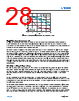
28 / 47 page  Data Sheet LT3046 analog.com Rev 0 28 of 47 Figure 72. Capacitor Voltage Coefficient for Different Case Sizes High Vibration Environments Voltage and temperature coefficients are not the only sources of problems. Some ceramic capacitors have a piezoelectric response. A piezoelectric device generates voltage across its terminals due to mechanical stress, similar to how a piezoelectric microphone works. For a ceramic capacitor, this stress can be induced by mechanical vibrations within the system or due to thermal transients. LT3046 applications in high-vibration environments have three distinct, piezoelectric noise generators: ceramic output, input, and SET pin capacitors. However, due to the low output impedance over a wide frequency range of the LT3046, negligible output noise is generated using a ceramic-output capacitor. Similarly, due to the ultra-high PSRR of the LT3046, negligible output noise is generated using a ceramic-input capacitor. Nonetheless, given the high SET pin impedance, any piezoelectric response from a ceramic SET pin capacitor generates significant output noise, peak-to-peak excursions of hundreds of mV. However, due to the high ESR and ESL tolerance of the SET pin capacitor, any nonpiezoelectrically responsive (tantalum, electrolytic, or film) capacitor can be used at the SET pin, although electrolytic capacitors tend to have high 1/f noise. In any case, use of a surface-mount capacitor is highly recommended. Stability and Input Capacitance The LT3046 is stable with a minimum 4.7μF IN pin capacitor. Analog Devices recommends using low ESR ceramic capacitors. In cases where long wires connect the power supply to the input and ground terminals of the LT3046, the use of low-value input capacitors combined with a large load current can result in instability. The resonant LC tank circuit formed by the wire inductance and the input capacitor is the cause of this instability and not the LT3046. The self-inductance, or isolated inductance, of a wire is directly proportional to its length. The wire diameter, however, has less influence on its self-inductance. For example, the self-inductance of a 2-AWG isolated wire with a diameter of 0.26in is about half the inductance of a 30-AWG wire with a diameter of 0.01in. One foot of 30-AWG wire has 465nH of self-inductance. Several methods exist to reduce the self-inductance of a wire. One method divides the current flowing toward the LT3046 between the two parallel conductors. In this case, placing the wires further apart reduces the inductance; up to a 50% reduction when placed only a few inches apart. Splitting the wires connects two equal inductors in parallel. However, when placed close to each other, their mutual inductance adds to the overall self-inductance of the wires; therefore, a 50% reduction is not possible in such cases. The second and more effective technique to MURATA: 25V, 10% X7R, 4.7µF CERAMIC 0805, 1.4mm THICK 1206, 1.8mm THICK 1210, 2.2mm THICK DC BIAS (V) 0 5 10 15 20 25 –100 –80 –60 –40 –20 0 20 |
|
Ligação URL |
| ALLDATASHEET é útil para você? [ DONATE ] |
Sobre Alldatasheet | Publicidade | Contato conosco | Privacy Policy | Link para a ficha técnica | roca de Link | Lista de Fabricantes All Rights Reserved©Alldatasheet.com |
| Russian : Alldatasheetru.com | Korean : Alldatasheet.co.kr | Spanish : Alldatasheet.es | French : Alldatasheet.fr | Italian : Alldatasheetit.com Portuguese : Alldatasheetpt.com | Polish : Alldatasheet.pl | Vietnamese : Alldatasheet.vn Indian : Alldatasheet.in | Mexican : Alldatasheet.com.mx | British : Alldatasheet.co.uk | New Zealand : Alldatasheet.co.nz |
|
Family Site : ic2ic.com |
icmetro.com |
 Portuguese ▼
 English
 Chinese
 German
 Japanese
 Russian
 Korean
 Spanish
 French
 Italian
 Portuguese
 Polish
 Vietnamese
 Indian
 Mexican
 British
 New Zealand