|
Os motores de busca de Datasheet de Componentes eletrônicos |
|
|
Os motores de busca de Datasheet de Componentes eletrônicos |
|
LTC3602 Folha de dados(PDF) 17 Page - Linear Technology |
|
|
|||||||||||||||||||||||||||||
LTC3602 Folha de dados(HTML) 17 Page - Linear Technology |
|
|
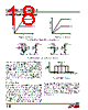
17 / 28 page  LTC3633A-2/LTC3633A-3 17 3633a23f steady-state value. During this recovery time, VOUT can be monitored for overshoot or ringing that would indicate a stability problem. When observing the response of VOUT to a load step, the initial output voltage step may not be within the bandwidth of the feedback loop, so the standard second order over- shoot/DC ratio cannot be used to determine phase margin. The output voltage settling behavior is related to the stability of the closed-loop system and will demonstrate the actual overall supply performance. For a detailed explanation of optimizing the compensation components, including a review of control loop theory, refer to Linear Technology Application Note 76. In some applications, a more severe transient can be caused by switching in loads with large (>10μF) input capacitors. The discharged input capacitors are effec- tively put in parallel with COUT, causing a rapid drop in VOUT. No regulator can deliver enough current to prevent this problem, if the switch connecting the load has low resistance and is driven quickly. The solution is to limit the turn-on speed of the load switch driver. A hot swap controller is designed specifically for this purpose and usually incorporates current limiting, short-circuit protec- tion, and soft starting. MODE/SYNC Operation The MODE/SYNC pin is a multipurpose pin allowing both mode selection and operating frequency synchronization. Floating this pin or connecting it to INTVCC enables Burst Mode operation for superior efficiency at low load currents at the expense of slightly higher output voltage ripple. When the MODE/SYNC pin is tied to ground, forced continuous mode operation is selected, creating the lowest fixed output ripple at the expense of light load efficiency. The LTC3633A-2 will detect the presence of the external clock signal on the MODE/SYNC pin and synchronize the internal oscillator to the phase and frequency of the in- coming clock. The presence of an external clock will place both regulators into forced continuous mode operation. APPLICATIONS INFORMATION Output Voltage Tracking and Soft-Start The LTC3633A-2 allows the user to control the output voltage ramp rate by means of the TRACKSS pin. From 0 to 0.6V, the TRACKSS voltage will override the internal 0.6V reference input to the error amplifier, thus regulating the feedback voltage to that of the TRACKSS pin. When TRACKSS is above 0.6V, tracking is disabled and the feed- back voltage will regulate to the internal reference voltage. The voltage at the TRACKSS pin may be driven from an external source, or alternatively, the user may leverage the internal 1.4μA pull-up current source to implement a soft-start function by connecting an external capacitor (CSS) from the TRACKSS pin to ground. The relationship between output rise time and TRACKSS capacitance is given by: tSS = 430000Ω • CSS A default internal soft-start ramp forces a minimum soft- start time of 400μs by overriding the TRACKSS pin input during this time period. Hence, capacitance values less than approximately 1000pF will not significantly affect soft-start behavior. When driving the TRACKSS pin from another source, each channel’s output can be set up to either coincidentally or ratiometrically track another supply’s output, as shown in Figure 5. In the following discussions, VOUT1 refers to the LTC3633A-2 output 1 as a master channel and VOUT2 refers to output 2 as a slave channel. In practice, either channel can be used as the master. To implement the coincident tracking in Figure 5a, con- nect an additional resistive divider to VOUT1 and connect its midpoint to the TRACKSS pin of the slave channel. The ratio of this divider should be the same as that of the slave channel’s feedback divider shown in Figure 6a. In this tracking mode, VOUT1 must be set higher than VOUT2. To implement the ratiometric tracking, the feedback pin of the master channel should connect to the TRACKSS pin of the slave channel (as in Figure 6b). By selecting different resistors, the LTC3633A-2 can achieve different modes of tracking including the two in Figure 5. |
|
Ligação URL |
| ALLDATASHEET é útil para você? [ DONATE ] |
Sobre Alldatasheet | Publicidade | Contato conosco | Privacy Policy | Link para a ficha técnica | roca de Link | Lista de Fabricantes All Rights Reserved©Alldatasheet.com |
| Russian : Alldatasheetru.com | Korean : Alldatasheet.co.kr | Spanish : Alldatasheet.es | French : Alldatasheet.fr | Italian : Alldatasheetit.com Portuguese : Alldatasheetpt.com | Polish : Alldatasheet.pl | Vietnamese : Alldatasheet.vn Indian : Alldatasheet.in | Mexican : Alldatasheet.com.mx | British : Alldatasheet.co.uk | New Zealand : Alldatasheet.co.nz |
|
Family Site : ic2ic.com |
icmetro.com |
 Portuguese ▼
 English
 Chinese
 German
 Japanese
 Russian
 Korean
 Spanish
 French
 Italian
 Portuguese
 Polish
 Vietnamese
 Indian
 Mexican
 British
 New Zealand