|
Os motores de busca de Datasheet de Componentes eletrônicos |
|
|
Os motores de busca de Datasheet de Componentes eletrônicos |
|
CC1010-RTY1 Folha de dados(PDF) 44 Page - Texas Instruments |
|
|
|||||||||||||||||||||||||||||
CC1010-RTY1 Folha de dados(HTML) 44 Page - Texas Instruments |
|
|
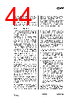
44 / 150 page  CC1010 SWRS047A Page 44 of 146 The Flash module can be set into different power modes using the control bits FLCON.FLASH_LP(1:0) introduced in the previous section. After reset, the Flash module is always active, drawing a static current of approximately 2.5 mA (at nominal operating conditions). However, to save power the Flash module can be set in a power-down mode between instructions in Active mode, and always in Idle or Power- Down mode. This will save approximately 1.5 mA of the Flash current consumption during operation in Active mode, and 2.5 mA during Idle or Power-Down mode. 15.15 In Circuit Debugging In order to facilitate a software monitor for in-circuit debugging/emulation capabilities a number of hardware support features have been implemented: A breakpoint instruction has been added to the 8051's instruction set. The instruction, given the mnemonic TRAP, is a single byte instruction with the opcode 0xA5. In the original 8051 the 0xA5 opcode is executed as a NOP instruction (opcode 0x00.) In the modified core this instruction raises a highest-level interrupt (Flash / Debug) by setting the corresponding interrupt flag EICON.FDIF and waiting a sufficient number of instruction cycles to allow the interrupt to take effect before the next instruction. The TRAP instruction can thus be written over the first byte (opcode) of any other instruction, the execution of which then will result in a branch to a software debugging monitor in the highest priority interrupt service routine. Single-stepping through instructions is supported since exactly one instruction is executed if an interrupt condition exists when returning from an interrupt service routine. Thus, single-stepping can be accomplished simply by not clearing the corresponding interrupt flag in the interrupt service routine associated with the software monitor. A second serial port has been added to enable debugging communication with a host PC without disrupting applications that use the main serial port for other purposes. Setting breakpoints and executing the instructions which have a breakpoint attached involves writing new data to the Flash instruction memory several times. Since the Flash memory can only withstand 20000 (typical) erase/write- cycles a simple instruction replacement mechanism has been implemented. This feature allows the surveillance of an address in the instruction memory space as defined in registers RADRL and RADRH. When this address is encountered on the Flash program memory address bus, the data returned on the data bus is replaced by the contents of register RDATA. Setting RADRH =RADRL=0 disables the replacement mechanism. This instruction replacement mechanism can be used in different ways: • A simple way of setting a single soft (not stored in FLASH) breakpoint, by setting RDATA to 0xA5 (the TRAP instruction) and RADR to the breakpoint address. • A simple way of restoring the original opcode byte of an instruction which has been subjected to a hard (stored in Flash) breakpoint, so that it can be executed (in single-step mode). • SFRs (hardware registers) can normally only be addressed directly (i.e. by hardwiring the specific address into the corresponding MOV instruction.) This would make code in a debug monitor, which returns the value of SFRs to a PC rather bloated. Using the instruction replacement mechanism on the operand byte of the move instruction instead of the opcode byte, allows indirect addressing of SFRs. Chipcon provides software for in-circuit debugging, which may be downloaded from the Chipcon homepage. This software uses the RESERVED register, |
|
Ligação URL |
| ALLDATASHEET é útil para você? [ DONATE ] |
Sobre Alldatasheet | Publicidade | Contato conosco | Privacy Policy | Link para a ficha técnica | roca de Link | Lista de Fabricantes All Rights Reserved©Alldatasheet.com |
| Russian : Alldatasheetru.com | Korean : Alldatasheet.co.kr | Spanish : Alldatasheet.es | French : Alldatasheet.fr | Italian : Alldatasheetit.com Portuguese : Alldatasheetpt.com | Polish : Alldatasheet.pl | Vietnamese : Alldatasheet.vn Indian : Alldatasheet.in | Mexican : Alldatasheet.com.mx | British : Alldatasheet.co.uk | New Zealand : Alldatasheet.co.nz |
|
Family Site : ic2ic.com |
icmetro.com |
 Portuguese ▼
 English
 Chinese
 German
 Japanese
 Russian
 Korean
 Spanish
 French
 Italian
 Portuguese
 Polish
 Vietnamese
 Indian
 Mexican
 British
 New Zealand