|
Os motores de busca de Datasheet de Componentes eletrônicos |
|
|
Os motores de busca de Datasheet de Componentes eletrônicos |
|
UCD3138064RGCR Folha de dados(PDF) 71 Page - Texas Instruments |
|
|
|
|||||||||||||||||||||||||||||
UCD3138064RGCR Folha de dados(HTML) 71 Page - Texas Instruments |
|
|
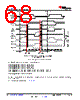
71 / 104 page  In addition, it is necessary to set the D2S_COMP_EN bit in the EADCCTRL register. This is for enabling the differential to single ended comparator function. The front end diagram leaves it out for simplicity, but the connection between the DAC and the EADC amplifier is actually differential. The PCMC comparator, however, is single ended. So a conversion is necessary as shown in Figure 10-9. EAP0 EAN0 DAC0 EADC 4 bit dithering gives 14 bits of effective resolution 97.65625μV/ LSB effective resolution X 6 bit ADC 8mV/LSB Signed 9 bit result (error) 1 mV /LSB AFE_GAIN 10 bit DAC 1. 5625mV/ LSB Value Dither Σ CPCC Filter x Ramp SAR/ Prebias Absolute Value Calculation Averaging 10 bit result 1.5625mV/LSB 2 3-AFE_GAIN Peak Current Mode Comparator Peak Current Detected Differential to Single Ended 2 AFE_GAIN Figure 10-9. Differential to Single-Ended Comparator Function The EADC_MODE bit in EADCCTRL should be set to a 5 for peak current mode. The peak current detection signal next goes to the Loop Mux. The Fault Mux has only 1 APCM input, but there are 3 front ends. So the PCM_FE_SEL bits in APCMCTRL must be used to select which front end is used: LoopMuxRegs.APCMCTRL.bit.PCM_FE_SEL = 2; // use FE2 for PCM */ The PCM_EN bit must also be set. LoopMuxRegs.APCMCTRL.bit.PCM_EN = 1; // Enable PCM Next the Fault Mux is used to enable the APCM bit to the CLIM/CBC signal to the DPWM. There are 4 DPWMxCLIM registers, one for each DPWM. The ANALOG_PCM_EN bit must be set in each one to connect the PCM detection signal to the CLIM/CBC signal on each DPWM. For the latest configuration information on all of these bits, consult the appropriate EVM firmware. To avoid errors, it is best to configure your hardware design using the same DPWMs, filters, and front ends for the same functions as the EVM. DPWM timing is used to trigger the start of the ramp. This is selected by the FECTRLxMUX registers in the Loop Mux. DPWMx_FRAME_SYNC_EN bits, when set, cause the ramp to be triggered at the start of the DPWM period. 10.2.2.5.3 Peak Current Mode (PCM) There is one peak current mode control module in the device however any front end can be configured to use this module. www.ti.com UCD3138064 SLUSB72D – MARCH 2013 – REVISED APRIL 2021 Copyright © 2021 Texas Instruments Incorporated Submit Document Feedback 71 Product Folder Links: UCD3138064 |
|
Ligação URL |
| ALLDATASHEET é útil para você? [ DONATE ] |
Sobre Alldatasheet | Publicidade | Contato conosco | Privacy Policy | Link para a ficha técnica | roca de Link | Lista de Fabricantes All Rights Reserved©Alldatasheet.com |
| Russian : Alldatasheetru.com | Korean : Alldatasheet.co.kr | Spanish : Alldatasheet.es | French : Alldatasheet.fr | Italian : Alldatasheetit.com Portuguese : Alldatasheetpt.com | Polish : Alldatasheet.pl | Vietnamese : Alldatasheet.vn Indian : Alldatasheet.in | Mexican : Alldatasheet.com.mx | British : Alldatasheet.co.uk | New Zealand : Alldatasheet.co.nz |
|
Family Site : ic2ic.com |
icmetro.com |
 Portuguese ▼
 English
 Chinese
 German
 Japanese
 Russian
 Korean
 Spanish
 French
 Italian
 Portuguese
 Polish
 Vietnamese
 Indian
 Mexican
 British
 New Zealand