|
Os motores de busca de Datasheet de Componentes eletrônicos |
|
|
Os motores de busca de Datasheet de Componentes eletrônicos |
|
UCD3138 Folha de dados(PDF) 61 Page - Texas Instruments |
|
|
|
|||||||||||||||||||||||||||||
UCD3138 Folha de dados(HTML) 61 Page - Texas Instruments |
|
|
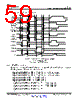
61 / 89 page  3 A – QB1 ( DPWM1 C) 3 B – QT1 ( DPWM 2 C) Controlled by DPWM1 Blanking register Blank B Begin Blank B End Period Start Period End Even 5 Even 6 Even 5 Even 6 Even 6 Controlled by DPWM2 Blanking register Blank B Begin Blank B End 61 UCD3138 www.ti.com SLUSAP2G – MARCH 2012 – REVISED SEPTEMBER 2016 Submit Documentation Feedback Product Folder Links: UCD3138 Application and Implementation Copyright © 2012–2016, Texas Instruments Incorporated These signals are actually routed to pins DPWM3A and 3B using the Intra Mux with these statements: Dpwm3Regs.DPWMCTRL0.bit.PWM_A_INTRA_MUX = 7; // Send DPWM1C Dpwm3Regs.DPWMCTRL0.bit.PWM_B_INTRA_MUX = 8; // Send DPWM2C Since these signals are really being used as events in the timer, the #defines are called EV5 and EV6. Here are the statements which initialize them: // Setup waveform for DPWM-C (re-using blanking B regs) Dpwm2Regs.DPWMBLKBBEG.all = PWM2_EV5 + (4 *16); Dpwm2Regs.DPWMBLKBEND.all = PWM2_EV6; Figure 7-5. Blank B Timing Information The statements for DPWM1 are the same. Remember that DPWMC reuses the Blank B registers for timing information. 7.2.2.5 Dynamic Signals to Bridge DPWM0 and 1 are set at normal mode. PCMC triggering signal (fault) chops DPWM0A and 1A cycle by cycle. The corresponding DPWM0B and 1B are used for synchronous rectifier MOSFET control. The same PCMC triggering signal is applied to DPWM2 and DPWM3. Both of these are set to normal mode as well. DPWM2 and 3 are chopped and their edges are used to generate the next two dynamic signals to the bridge. They are generated using the Edge Generator Module in DPWM2. The Edge Generator sources are DPWM2 and DPWM3. The edges used are: DPWM2A turned on by a rising edge on DPWM2BF DPWM2A turned off by a falling edge on DPWM3AF DPWM2B turned on by a rising edge on DPWM3BF DPWM2B turned off by a falling edge on DPWM2AF |
|
Ligação URL |
| ALLDATASHEET é útil para você? [ DONATE ] |
Sobre Alldatasheet | Publicidade | Contato conosco | Privacy Policy | Link para a ficha técnica | roca de Link | Lista de Fabricantes All Rights Reserved©Alldatasheet.com |
| Russian : Alldatasheetru.com | Korean : Alldatasheet.co.kr | Spanish : Alldatasheet.es | French : Alldatasheet.fr | Italian : Alldatasheetit.com Portuguese : Alldatasheetpt.com | Polish : Alldatasheet.pl | Vietnamese : Alldatasheet.vn Indian : Alldatasheet.in | Mexican : Alldatasheet.com.mx | British : Alldatasheet.co.uk | New Zealand : Alldatasheet.co.nz |
|
Family Site : ic2ic.com |
icmetro.com |
 Portuguese ▼
 English
 Chinese
 German
 Japanese
 Russian
 Korean
 Spanish
 French
 Italian
 Portuguese
 Polish
 Vietnamese
 Indian
 Mexican
 British
 New Zealand