|
Os motores de busca de Datasheet de Componentes eletrônicos |
|
|
Os motores de busca de Datasheet de Componentes eletrônicos |
|
LTC1291 Folha de dados(PDF) 18 Page - Linear Technology |
|
|
|||||||||||||||||||||||||||||
LTC1291 Folha de dados(HTML) 18 Page - Linear Technology |
|
|
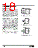
18 / 20 page  18 LTC1291 S APPLICATI I FOR ATIO Overvoltage Protection Applying signals to the LTC1291’s analog inputs that exceed the positive supply or that go below ground will degrade the accuracy of the A/D and possibly damage the device. For example this condition would occur if a signal is applied to the analog inputs before power is applied to the LTC1291. It can also happen if the input source is operating from supplies of larger value than the LTC1291 supply. These conditions should be prevented either with proper supply sequencing or by use of external circuitry to clamp or current limit the input source. There are two ways to protect the inputs. In Figure 13 diode clamps from the inputs to VCC and GND are used. The second method is to put resistors in series with the analog inputs for current limiting. Limit the current to 15mA per channel. The +IN input can accept a resistor value of 1k but the –IN input cannot accept more than 250 Ωwhenclocked at its maximum clock frequency of 1MHz. If the LTC1291 is clocked at the maximum clock frequency and 250 Ω is not enough to current limit the input source then the clamp diodes are recommended (Figures 14 and 15). The reason for the limit on the resistor value is the MSB bit test is affected by the value of the resistor placed at the –IN input (see discussion on Analog Inputs and the typical perfor- mance characteristics Maximum CLK Frequency vs Source Resistance). Because a unique input protection structure is used on the digital input pins, the signal levels on these pins can exceed the device VCC without damaging the device. 5V LTC1291 F13 CH0 GND DIN DOUT CLK VCC (VREF) CS CH1 1N4148 DIODES LTC1291 5V LTC1291 F14 CH0 GND DIN DOUT CLK CS CH1 250 Ω 1k LTC1291 VCC (VREF) 5V LTC1291 F15 CH0 GND DIN DOUT CLK CS CH1 LTC1291 1N4148 DIODES 1k VCC (VREF) Figure 13. Overvoltage Protection for Inputs Figure 14. Overvoltage Protection for Inputs Figure 15. Overvoltage Protection for Inputs |
|
|
Ligação URL |
| ALLDATASHEET é útil para você? [ DONATE ] |
Sobre Alldatasheet | Publicidade | Contato conosco | Privacy Policy | Link para a ficha técnica | roca de Link | Lista de Fabricantes All Rights Reserved©Alldatasheet.com |
| Russian : Alldatasheetru.com | Korean : Alldatasheet.co.kr | Spanish : Alldatasheet.es | French : Alldatasheet.fr | Italian : Alldatasheetit.com Portuguese : Alldatasheetpt.com | Polish : Alldatasheet.pl | Vietnamese : Alldatasheet.vn Indian : Alldatasheet.in | Mexican : Alldatasheet.com.mx | British : Alldatasheet.co.uk | New Zealand : Alldatasheet.co.nz |
|
Family Site : ic2ic.com |
icmetro.com |
 Portuguese ▼
 English
 Chinese
 German
 Japanese
 Russian
 Korean
 Spanish
 French
 Italian
 Portuguese
 Polish
 Vietnamese
 Indian
 Mexican
 British
 New Zealand