|
Os motores de busca de Datasheet de Componentes eletrônicos |
|
|
Os motores de busca de Datasheet de Componentes eletrônicos |
|
AT89LS53 Folha de dados(PDF) 20 Page - ATMEL Corporation |
|
|
|||||||||||||||||||||||||||||
AT89LS53 Folha de dados(HTML) 20 Page - ATMEL Corporation |
|
|
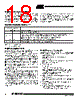
20 / 35 page  AT89LS53 0851C–MICRO–3/06 20 Instruction Set Notes: 1. DATA polling is used to indicate the end of a write cycle which typically takes less than 10 ms at 2.7V. 2. “x” = don’t care. Instruction Input Format Operation Byte 1 Byte 2 Byte 3 Programming Enable 1010 1100 0101 0011 xxxx xxxx Enable serial programming interface after RST goes high. Chip Erase 1010 1100 xxxx x100 xxxx xxxx Chip erase the 12K memory array. Read Code Memory low addr xxxx xxxx Read data from Code memory array at the selected address. The 6 MSBs of the first byte are the high order address bits. The low order address bits are in the second byte. Data are available at pin MISO during the third byte. Write Code Memory low addr data in Write data to Code memory location at selected address. The address bits are the 6 MSBs of the first byte together with the second byte. Write Lock Bits 1010 1100 xxxx xxxx Write lock bits. Set LB1, LB2 or LB3 = “0” to program lock bits. Serial Programming Algorithm To program and verify the AT89LS53 in the serial program- ming mode, the following sequence is recommended: 1. Power-up sequence: Apply power between VCC and GND pins. Set RST pin to “H”. If a crystal is not connected across pins XTAL1 and XTAL2, apply a 3 MHz to 12 MHz clock to XTAL1 pin and wait for at least 10 milliseconds. 2. Enable serial programming by sending the Pro- gramming Enable serial instruction to pin MOSI/ P1.5. The frequency of the shift clock supplied at pin SCK/P1.7 needs to be less than the CPU clock at XTAL1 divided by 40. 3. The Code array is programmed one byte at a time by supplying the address and data together with the appropriate Write instruction. The selected memory location is first automatically erased before new data is written. The write cycle is self-timed and typ- ically takes less than 2.5 ms at 5V and less than 10 ms at 2.7V. 4. Any memory location can be verified by using the Read instruction which returns the content at the selected address at serial output MISO/P1.6. 5. At the end of a programming session, RST can be set low to commence normal operation. Power-off sequence (if needed): Set XTAL1 to “L” (if a crystal is not used). Set RST to “L”. Turn VCC power off. Serial Programming Instruction The Instruction Set for Serial Programming follows a 3-byte protocol and is shown in the following table: 01 10 xx111 |
|
Ligação URL |
| ALLDATASHEET é útil para você? [ DONATE ] |
Sobre Alldatasheet | Publicidade | Contato conosco | Privacy Policy | Link para a ficha técnica | roca de Link | Lista de Fabricantes All Rights Reserved©Alldatasheet.com |
| Russian : Alldatasheetru.com | Korean : Alldatasheet.co.kr | Spanish : Alldatasheet.es | French : Alldatasheet.fr | Italian : Alldatasheetit.com Portuguese : Alldatasheetpt.com | Polish : Alldatasheet.pl | Vietnamese : Alldatasheet.vn Indian : Alldatasheet.in | Mexican : Alldatasheet.com.mx | British : Alldatasheet.co.uk | New Zealand : Alldatasheet.co.nz |
|
Family Site : ic2ic.com |
icmetro.com |
 Portuguese ▼
 English
 Chinese
 German
 Japanese
 Russian
 Korean
 Spanish
 French
 Italian
 Portuguese
 Polish
 Vietnamese
 Indian
 Mexican
 British
 New Zealand