|
Os motores de busca de Datasheet de Componentes eletrônicos |
|
|
Os motores de busca de Datasheet de Componentes eletrônicos |
|
AT89LS53 Folha de dados(PDF) 7 Page - ATMEL Corporation |
|
|
|||||||||||||||||||||||||||||
AT89LS53 Folha de dados(HTML) 7 Page - ATMEL Corporation |
|
|
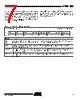
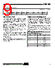
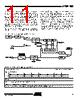
7 / 35 page  7 AT89LS53 0851C–MICRO–3/06 Dual Data Pointer Registers To facilitate accessing exter- nal data memory, two banks of 16 bit Data Pointer Regis- ters are provided: DP0 at SFR address locations 82H-83H and DP1 at 84H-85H. Bit DPS = 0 in SFR WCON selects DP0 and DPS = 1 selects DP1. The user should always ini- talize the DPS bit to the appropriate value before accessing the respective Data Pointer register. Power Off Flag The Power Off Flag (POF) is located at bit_4 (PCON.4) in the PCON SFR. POF is set to “1” during power up. It can be set and reset under software control and is not affected by RESET. Table 3. WCON—Watchdog Control Register WCON Address = 96H Reset Value = 0000 0010B PS2 PS1 PS0 reserved reserved DPS WDTRST WDTEN Bit 7 65 432 10 Symbol Function PS2 PS1 PS0 Prescaler Bits for the Watchdog Timer. When all three bits are set to “0”, the watchdog timer has a nominal period of 16 ms. When all three bits are set to “1”, the nominal period is 2048 ms. DPS Data Pointer Register Select. DPS = 0 selects the first bank of Data Pointer Register, DP0, and DPS = 1 selects the second bank, DP1 WDTRST Watchdog Timer Reset. Each time this bit is set to “1” by user software, a pulse is generated to reset the watchdog timer. The WDTRST bit is then automatically reset to “0” in the next instruction cycle. The WDTRST bit is Write-Only. WDTEN Watchdog Timer Enable Bit. WDTEN = 1 enables the watchdog timer and WDTEN = 0 disables the watchdog timer. |
|
Ligação URL |
| ALLDATASHEET é útil para você? [ DONATE ] |
Sobre Alldatasheet | Publicidade | Contato conosco | Privacy Policy | Link para a ficha técnica | roca de Link | Lista de Fabricantes All Rights Reserved©Alldatasheet.com |
| Russian : Alldatasheetru.com | Korean : Alldatasheet.co.kr | Spanish : Alldatasheet.es | French : Alldatasheet.fr | Italian : Alldatasheetit.com Portuguese : Alldatasheetpt.com | Polish : Alldatasheet.pl | Vietnamese : Alldatasheet.vn Indian : Alldatasheet.in | Mexican : Alldatasheet.com.mx | British : Alldatasheet.co.uk | New Zealand : Alldatasheet.co.nz |
|
Family Site : ic2ic.com |
icmetro.com |
 Portuguese ▼
 English
 Chinese
 German
 Japanese
 Russian
 Korean
 Spanish
 French
 Italian
 Portuguese
 Polish
 Vietnamese
 Indian
 Mexican
 British
 New Zealand