|
Os motores de busca de Datasheet de Componentes eletrônicos |
|
|
Os motores de busca de Datasheet de Componentes eletrônicos |
|
AN3095 Folha de dados(PDF) 41 Page - STMicroelectronics |
|
|
|||||||||||||||||||||||||||||
AN3095 Folha de dados(HTML) 41 Page - STMicroelectronics |
|
|
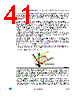
41 / 55 page  AN3095 STM32F103xx-based current control strategy for inverter grid connection Doc ID 16555 Rev 3 41/55 The grid voltage and the 90° phase-shifted voltage are used to perform the reference frame change, or “park transformation”, and create two voltage components on the DQ reference frame called Vd and Vq. One of the two components is controlled to zero with a PI regulator. The output of the PI regulator is the grid frequency which may be integrated to obtain the grid angle. It is worth knowing that if the Vq component is controlled to zero then the Vd component follows the grid-voltage rotation. In this case, the active power injected into the grid may be controlled, transforming the current in the same reference frame and by acting on the amplitude of the Id component. The Iq component must also be controlled in order to ensure zero reactive power injection. On the contrary, if the Vq component is controlled to zero in the PLL, the active power is controlled with the Iq current component and the Id current component is used to control the reactive power to zero or to the desired value. This said, the advantages of such a control structure are clear: first of all the current components on the synchronous reference frame are constants and may then be controlled with standard PI regulators ensuring zero steady-state error; the second advantage is a decoupled control of active and reactive power. The reference values for the active and reactive component of the current are set by two additional PI regulators in the outer control loop. The active reference current component is generated by confronting the DC bus voltage with the reference voltage value. The error between the actual value and the reference DC bus voltage is sent to a PI regulator whose output is the active current component value (Figure 26). Similarly, the reactive current reference value is set by another PI regulator whose input is the error generated between the reactive power command and the actual estimated value. Figure 27. DQ components of the current The difference between reference components of the current and the actual DQ components are the inputs of the PI regulators in the inner control loop. The outputs of the PI regulators in the inner loop are two voltage components, Vd and Vq. By performing a reverse park transformation, two AC voltages are generated back to the stationary reference frame, and therefore the generation of the modulating signals of the DC-AC converter may be executed by the microcontroller. The amount of power injected into the grid depends on the power available from the PV array. This power is then processed by the DC-DC converter which is controlled in order to maximize the energy yield from the array, independent to temperature variations and irradiation conditions, by controlling its input impedance. The control of the input impedance requires both PV array current and voltage sensing and some simple calculations executed |
|
Ligação URL |
| ALLDATASHEET é útil para você? [ DONATE ] |
Sobre Alldatasheet | Publicidade | Contato conosco | Privacy Policy | Link para a ficha técnica | roca de Link | Lista de Fabricantes All Rights Reserved©Alldatasheet.com |
| Russian : Alldatasheetru.com | Korean : Alldatasheet.co.kr | Spanish : Alldatasheet.es | French : Alldatasheet.fr | Italian : Alldatasheetit.com Portuguese : Alldatasheetpt.com | Polish : Alldatasheet.pl | Vietnamese : Alldatasheet.vn Indian : Alldatasheet.in | Mexican : Alldatasheet.com.mx | British : Alldatasheet.co.uk | New Zealand : Alldatasheet.co.nz |
|
Family Site : ic2ic.com |
icmetro.com |
 Portuguese ▼
 English
 Chinese
 German
 Japanese
 Russian
 Korean
 Spanish
 French
 Italian
 Portuguese
 Polish
 Vietnamese
 Indian
 Mexican
 British
 New Zealand