|
Os motores de busca de Datasheet de Componentes eletrônicos |
|
|
Os motores de busca de Datasheet de Componentes eletrônicos |
|
AN3095 Folha de dados(PDF) 12 Page - STMicroelectronics |
|
|
|||||||||||||||||||||||||||||
AN3095 Folha de dados(HTML) 12 Page - STMicroelectronics |
|
|
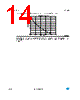
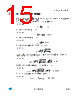
12 / 55 page  DC-DC converter AN3095 12/55 Doc ID 16555 Rev 3 Due to symmetry during the two halves of the switching period, current expressions and current paths may be derived with similar considerations for the second half of the switching period. If d >1 the current in the leakage inductor may reach zero and there is a boundary between CCM and DCM. In DCM there are also three modes of operation, as shown in Figure 10. ● Mode 1, interval t0-t1: At t=t0 inductor current is zero. After t=t0 devices M1and M4 are turned on under zero current and inductor current rises according to the following equation: Equation 5 Figure 10. Modulation and transformer current in DCM ● Mode 2, interval t1-t2: At t1 M6 turns off and M5 turns on with zero current. Inductor current expression is given by: Equation 6 and reaches zero at t=t3. ● Mode 3, t2-t3 Equation 7 The boundary between DCM and CCM depends on the phase-shift angle, input voltage, output voltage and transformer turns ratio and is given by: ( ) ) t ( i t t V L 1 ) t ( i Lk 1 in k k L + − = t0 t1 t2 t3 AM05604v1 ()( ) ) t ( i t t d 1 V L 1 ) t ( i 2 Llk 2 in k K L + − − = 0 ) t ( i K L = |
|
Ligação URL |
| ALLDATASHEET é útil para você? [ DONATE ] |
Sobre Alldatasheet | Publicidade | Contato conosco | Privacy Policy | Link para a ficha técnica | roca de Link | Lista de Fabricantes All Rights Reserved©Alldatasheet.com |
| Russian : Alldatasheetru.com | Korean : Alldatasheet.co.kr | Spanish : Alldatasheet.es | French : Alldatasheet.fr | Italian : Alldatasheetit.com Portuguese : Alldatasheetpt.com | Polish : Alldatasheet.pl | Vietnamese : Alldatasheet.vn Indian : Alldatasheet.in | Mexican : Alldatasheet.com.mx | British : Alldatasheet.co.uk | New Zealand : Alldatasheet.co.nz |
|
Family Site : ic2ic.com |
icmetro.com |
 Portuguese ▼
 English
 Chinese
 German
 Japanese
 Russian
 Korean
 Spanish
 French
 Italian
 Portuguese
 Polish
 Vietnamese
 Indian
 Mexican
 British
 New Zealand