ü
8-33
8
Preliminary
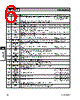
Product Description
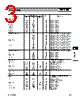
Ordering Information
Typical Applications
Features
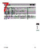
Functional Block Diagram
RF Micro Devices, Inc.
7625 Thorndike Road
Greensboro, NC 27409, USA
Tel (336) 664 1233
Fax (336) 664 0454
http://www.rfmd.com
Optimum Technology Matching® Applied
Si BJT
GaAs MESFET
GaAs HBT
Si Bi-CMOS
SiGe HBT
Si CMOS
LNAIPSEL
LNA ISET
X2 ENABLE
BAND SEL
IF SEL
32
31
17
10
9
LOGIC
CONTROL
PCS LNA IN
CELL LNA IN
LNA GAIN SEL
MIX GAIN SEL
11
14
12
30
25
23
4
5
7
8
19
20
21
22
1
18
15
PCS LO OUT -
CELL LO OUT+
CELL LO OUT-
PCS LO OUT+
IF1+
IF2+
IF1-
IF2-
X2
RF2492
DUAL-BAND LOW NOISE AMPLIFIER/MIXER
• TDMA-GSM Cellular/PCS Handsets
• TDMA Cellular/PCS Handsets
• GAIT Handsets
• CDMA Cellular/PCS Handsets
• GSM DCS/PCS Handsets
The RF2492 is a fully featured dual-band LNA/Mixer and
is usable in a variety of mobile handset applications. The
unique dual IF outputs provide interface to two indepen-
dent IF SAW filters supporting applications such as
TDMA-EDGE where 30kHz and 200 kHz bandwidth SAW
filters are used. With independent power management
control pins for the LNAs and mixers, either IF output can
be accessed from either high- or low-band LNAs, provid-
ing maximum flexibility with minimum power usage. Multi-
ple gain control options are provided to achieve a very
large dynamic range for the receiver. A frequency doubler
is included in the LO circuit to generate both high- and
low-band LO signals with a single VCO. The RF2492 is
packaged in a 32 pin, 5mmx5mm, leadless plastic pack-
age.
• Complete Dual-Band Receiver Front End
• Low Noise Figure
• Stepped LNA/Mixer Gain Control
• Adjustable LNA Bias Current/IIP3
• Integrated LO Frequency Doubler
• Differential LO Buffer Outputs
RF2492
Dual-Band Low Noise Amplifier/Mixer
RF2492 PCBA
Fully Assembled Evaluation Board
8
Rev A4 010828
1.00
0.85
5.00
sq.
NOTES:
Shaded Pin is Lead 1.
1
Package Warpage: 0.05 mm max.
4
Die Thickness Allowable: 0.305 mm max.
5
Pin 1 identifier must exist on top surface of package by identification
mark or feature on the package body. Exact shape and size is optional.
2
Dimension applies to plated terminal: to be measured between 0.02 mm
and 0.25 mm from terminal end.
3
0.30
0.18
3
0.60
0.24 typ
0.55
0.30
0.50
0.23
0.13
4PLCS
0.45
0.20
4PLCS
0.05
0.01
0.80
0.65
3.25
2.95 sq.
12°
MAX
Package Style: LCC, 32-Pin, 5x5


 Portuguese ▼
 English
 Chinese
 German
 Japanese
 Russian
 Korean
 Spanish
 French
 Italian
 Portuguese
 Polish
 Vietnamese
 Indian
 Mexican
 British
 New Zealand