|
Os motores de busca de Datasheet de Componentes eletrônicos |
|
|
Os motores de busca de Datasheet de Componentes eletrônicos |
|
LCVT Folha de dados(PDF) 10 Page - Linear Technology |
|
|
|||||||||||||||||||||||||||||
LCVT Folha de dados(HTML) 10 Page - Linear Technology |
|
|
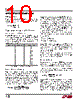
10 / 24 page  LT3684 10 3684f FB Resistor Network The output voltage is programmed with a resistor divider between the output and the FB pin. Choose the 1% resis- tors according to: RR VOUT 12 1 265 1 = ⎛ ⎝⎜ ⎞ ⎠⎟ . – Reference designators refer to the Block Diagram. Setting the Switching Frequency The LT3684 uses a constant frequency PWM architecture that can be programmed to switch from 300kHz to 2.8MHz by using a resistor tied from the RT pin to ground. A table showing the necessary RT value for a desired switching frequency is in Figure 1. SWITCHING FREQUENCY (MHz) RT VALUE (kΩ) 0.2 0.3 0.4 0.6 0.8 1.0 1.2 1.4 1.6 1.8 2.0 2.2 2.4 2.6 2.8 267 187 133 84.5 60.4 45.3 36.5 29.4 23.7 20.5 16.9 14.3 12.1 10.2 8.66 Operating Frequency Tradeoffs Selection of the operating frequency is a tradeoff between efficiency, component size, minimum dropout voltage, and maximum input voltage. The advantage of high frequency operation is that smaller inductor and capacitor values may be used. The disadvantages are lower efficiency, lower maximum input voltage, and higher dropout voltage. The highest acceptable switching frequency (fSW(MAX)) for a given application can be calculated as follows: f VV tV V V SW MAX D OUT ON MIN DIN SW () () = + + () – where VIN is the typical input voltage, VOUT is the output voltage, is the catch diode drop (~0.5V), VSW is the internal switch drop (~0.5V at max load). This equation shows that slower switching frequency is necessary to safely accommodate high VIN/VOUT ratio. Also, as shown in the next section, lower frequency allows a lower dropout voltage. The reason input voltage range depends on the switching frequency is because the LT3684 switch has finite minimum on and off times. The switch can turn on for a minimum of ~150ns and turn off for a minimum of ~150ns. This means that the minimum and maximum duty cycles are: DC f t DC f t MIN SW ON MIN MAX SW OFF MIN = = () () 1– where fSW is the switching frequency, the tON(MIN) is the minimum switch on time (~150ns), and the tOFF(MIN) is the minimum switch off time (~150ns). These equations show that duty cycle range increases when switching frequency is decreased. A good choice of switching frequency should allow ad- equate input voltage range (see next section) and keep the inductor and capacitor values small. Input Voltage Range The maximum input voltage for LT3684 applications de- pends on switching frequency, the Absolute Maximum Rat- ings on VIN and BOOST pins, and on operating mode. If the output is in start-up or short-circuit operating modes, then VIN must be below 34V and below the result of the following equation: V VV ft VV IN MAX OUT D SW ON MIN DSW () () = + + – where VIN(MAX) is the maximum operating input voltage, VOUT is the output voltage, VD is the catch diode drop (~0.5V), VSW is the internal switch drop (~0.5V at max load), fSW is the switching frequency (set by RT), and tON(MIN)istheminimumswitchontime(~150ns).Notethat a higher switching frequency will depress the maximum operating input voltage. Conversely, a lower switching Figure 1. Switching Frequency vs RT Value APPLICATIONS INFORMATION |
|
|
Ligação URL |
| ALLDATASHEET é útil para você? [ DONATE ] |
Sobre Alldatasheet | Publicidade | Contato conosco | Privacy Policy | Link para a ficha técnica | roca de Link | Lista de Fabricantes All Rights Reserved©Alldatasheet.com |
| Russian : Alldatasheetru.com | Korean : Alldatasheet.co.kr | Spanish : Alldatasheet.es | French : Alldatasheet.fr | Italian : Alldatasheetit.com Portuguese : Alldatasheetpt.com | Polish : Alldatasheet.pl | Vietnamese : Alldatasheet.vn Indian : Alldatasheet.in | Mexican : Alldatasheet.com.mx | British : Alldatasheet.co.uk | New Zealand : Alldatasheet.co.nz |
|
Family Site : ic2ic.com |
icmetro.com |
 Portuguese ▼
 English
 Chinese
 German
 Japanese
 Russian
 Korean
 Spanish
 French
 Italian
 Portuguese
 Polish
 Vietnamese
 Indian
 Mexican
 British
 New Zealand