|
Os motores de busca de Datasheet de Componentes eletrônicos |
|
|
Os motores de busca de Datasheet de Componentes eletrônicos |
|
LCVT Folha de dados(PDF) 7 Page - Linear Technology |
|
|
|||||||||||||||||||||||||||||
LCVT Folha de dados(HTML) 7 Page - Linear Technology |
|
|
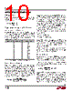
7 / 24 page  LT3684 7 3684f BD (Pin 1): This pin connects to the anode of the boost Schottky diode. BOOST (Pin 2): This pin is used to provide a drive voltage, higher than the input voltage, to the internal bipolar NPN power switch. SW (Pin 3): The SW pin is the output of the internal power switch. Connect this pin to the inductor, catch diode and boost capacitor. VIN (Pin 4): The VIN pin supplies current to the LT3684’s internal regulator and to the internal power switch. This pin must be locally bypassed. RUN/SS (Pin 5): The RUN/SS pin is used to put the LT3684 in shutdown mode. Tie to ground to shut down the LT3684. Tie to 2.3V or more for normal operation. If the shutdown feature is not used, tie this pin to the VIN pin. RUN/SS also provides a soft-start function; see the Applications Information section. PG (Pin 6): The PG pin is the open collector output of an internal comparator. PG remains low until the FB pin is within 10% of the final regulation voltage. PG output is valid when VIN is above 3.5V and RUN/SS is high. BIAS (Pin 7): The BIAS pin supplies the current to the LT3684’s internal regulator. Tie this pin to the lowest available voltage source above 3V (typically VOUT). This architecture increases efficiency especially when the input voltage is much higher than the output. FB (Pin 8): The LT3684 regulates the FB pin to 1.265V. Connect the feedback resistor divider tap to this pin. VC (Pin 9): The VC pin is the output of the internal error amplifier. The voltage on this pin controls the peak switch current. Tie an RC network from this pin to ground to compensate the control loop. RT (Pin 10): Oscillator Resistor Input. Connecting a resistor to ground from this pin sets the switching frequency. Exposed Pad (Pin 11): Ground. The Exposed Pad must be soldered to PCB. PIN FUNCTIONS |
|
|
Ligação URL |
| ALLDATASHEET é útil para você? [ DONATE ] |
Sobre Alldatasheet | Publicidade | Contato conosco | Privacy Policy | Link para a ficha técnica | roca de Link | Lista de Fabricantes All Rights Reserved©Alldatasheet.com |
| Russian : Alldatasheetru.com | Korean : Alldatasheet.co.kr | Spanish : Alldatasheet.es | French : Alldatasheet.fr | Italian : Alldatasheetit.com Portuguese : Alldatasheetpt.com | Polish : Alldatasheet.pl | Vietnamese : Alldatasheet.vn Indian : Alldatasheet.in | Mexican : Alldatasheet.com.mx | British : Alldatasheet.co.uk | New Zealand : Alldatasheet.co.nz |
|
Family Site : ic2ic.com |
icmetro.com |
 Portuguese ▼
 English
 Chinese
 German
 Japanese
 Russian
 Korean
 Spanish
 French
 Italian
 Portuguese
 Polish
 Vietnamese
 Indian
 Mexican
 British
 New Zealand