|
Os motores de busca de Datasheet de Componentes eletrônicos |
|
|
Os motores de busca de Datasheet de Componentes eletrônicos |
|
EVAL-CN0575-RPIZ Folha de dados(PDF) 6 Page - Analog Devices |
|
|
|||||||||||||||||||||||||||||
EVAL-CN0575-RPIZ Folha de dados(HTML) 6 Page - Analog Devices |
|
|
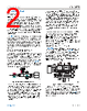
6 / 7 page  Circuit Note CN-0575 analog.com Rev. 0 | 6 of 7 EQUIPMENT NEEDED ► EVAL-CN0575-RPIZ ► EVAL-ADIN1100-EBZ ► 24 V (Class 12) or 55 V (Class 13) power supply ► Raspberry Pi computer (Model 3B+ or above) ► Host PC (Windows/Linux/Mac) ► CN0575 demo Python script ► Plug-in screw-terminal connector ► Single-pair of 18 AWG (max) wires ► Category 5e Ethernet cable with RJ45 connectors ► USB-A to micro-USB-B cable GETTING STARTED Before proceeding with the test, the Raspberry Pi must be config- ured with the latest ADI Kuiper Linux image and set to use the CN0575 device tree. For a detailed procedure on how to set up the Raspberry Pi, refer to the EVAL-CN0575-RPIZ User Guide. SETUP AND TEST To establish a 10BASE-T1L connection to a Raspberry Pi using the EVAL-CN0575-RPIZ, follow below procedure: 1. Connect the EVAL-CN0575-RPIZ to the Raspberry Pi via the 40-pin interface connector. 2. Set the output of the DC power supply to either 24 V (Class 12) or 55 V (Class 13), depending on the setting of JP1 and JP2 on the EVAL-CN0575-RPIZ. 3. Screw in one end of the single pair of wires to the terminal block of the EVAL-CN0575-RPIZ. 4. Screw in the other end to the plug-in connector on the EVAL- ADIN1100-EBZ. 5. Screw in the other end of the twisted pair into the EVAL- ADIN1100-EBZ 10BASE-T1L terminal block. 6. Using the Ethernet cable and the micro-USB cable, connect the EVAL-ADIN1100-EBZ to the host PC. Figure 8. CN0575 Test Setup 7. The LINK LED on the EVAL-CN0575-RPIZ and the LED_0 LED on the EVAL-ADIN1100-EBZ must turn on and start blinking at the same time to indicate a successful link. 8. On the host PC, use remote access software (PuTTY, VNC viewer) to log into and control the Raspberry Pi. 9. Open Python on the remote host and run the CN0575 example script, as shown in Figure 9. The CPU temperature and ADT75 will display, the on-board ALERT LED starts blinking, and the state of the TEST button will be displayed. Figure 9. CN0575 Example Script |
|
|
Ligação URL |
| ALLDATASHEET é útil para você? [ DONATE ] |
Sobre Alldatasheet | Publicidade | Contato conosco | Privacy Policy | Link para a ficha técnica | roca de Link | Lista de Fabricantes All Rights Reserved©Alldatasheet.com |
| Russian : Alldatasheetru.com | Korean : Alldatasheet.co.kr | Spanish : Alldatasheet.es | French : Alldatasheet.fr | Italian : Alldatasheetit.com Portuguese : Alldatasheetpt.com | Polish : Alldatasheet.pl | Vietnamese : Alldatasheet.vn Indian : Alldatasheet.in | Mexican : Alldatasheet.com.mx | British : Alldatasheet.co.uk | New Zealand : Alldatasheet.co.nz |
|
Family Site : ic2ic.com |
icmetro.com |
 Portuguese ▼
 English
 Chinese
 German
 Japanese
 Russian
 Korean
 Spanish
 French
 Italian
 Portuguese
 Polish
 Vietnamese
 Indian
 Mexican
 British
 New Zealand