|
Os motores de busca de Datasheet de Componentes eletrônicos |
|
|
Os motores de busca de Datasheet de Componentes eletrônicos |
|
EVAL-CN0575-RPIZ Folha de dados(PDF) 5 Page - Analog Devices |
|
|
|||||||||||||||||||||||||||||
EVAL-CN0575-RPIZ Folha de dados(HTML) 5 Page - Analog Devices |
|
|
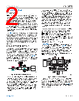
5 / 7 page  Circuit Note CN-0575 analog.com Rev. 0 | 5 of 7 ISOLATED FLYBACK CONVERTER CIRCUIT DESIGN An LT8304 flyback converter is used to supply the 5 V power required by the host Raspberry Pi. This device can accept an input voltage between 3 V and 100 V and deliver up to 24 W of isolated output power, allowing it to easily operate in SPoE PD Classes 12 and 13. Figure 6 shows the isolated flyback circuit configuration for the CN0575. Figure 6. LT8304 Flyback Converter Circuit In CN0575, the LT8304 uses a flyback transformer with a turns ratio of 6:1 and a primary inductance of 40 μH to produce the isolated power. As recommended in the LT8304 data sheet, an RC and Schottky/Zener snubber is additionally connected across the primary windings of the transformer to protect the device from high voltage spikes generated by leakage inductance. A diode is used to provide rectification on the secondary side, and is rated for a forward current of 10 A and a reverse voltage of 45 V. Three 100 μF capacitors are used to reduce the ripple of the output voltage. This combination of components allows the design to meet the power requirements for Class 12 and Class 13 devices, as well as support the operating requirements of the LT8304. For the general design procedure in selecting these components, refer to the LT8304 data sheet. The output voltage of the LT8304 is set by an external feedback resistor connected between the SW and RFB pins; the value of which is calculated using Equation 2: RFB=RREF×NPS×VOUT+VF VREF (2) where: RFB is the feedback resistance in kΩ. RREF is the reference resistance in kΩ. VREF is the internal reference voltage in V. NPS is the transformer effective primary-to-secondary turns ratio. VOUT is the output voltage. VF is the output diode forward voltage. For the required output voltage of 5 V, a 6:1 transformer turns ratio, 1 V VREF, 10 k RREF, and an output diode forward voltage of 0.3 V, the equation results in an RFB value of 318 kΩ; the closest standard 1% value of 316 kΩ is used. As shown in Figure 7, these specifications allow the LT8304 to supply more than 2 A of load current — more than adequate for Classes 12 and 13, which only require 1.68 A and 1.54 A, respectively for 5 V. Figure 7. LT8304 Load Regulation for Class 12 and Class 13 Operation MINIMAL FIELD DEVICE The CN0575 can be used as a basic temperature sensing field device using an on-board ADT75 digital temperature sensor. This device is ideal for a minimal complete temperature monitoring application. The only external components required for its operation are a decoupling capacitor for the supply pin, and pull-up resistors for the I2C lines. In addition to the ADT75, the CN0575 also includes a push button and an LED as basic GPIO devices that can be used to provide remote user input/output. Additional Raspberry Pi peripheral hard- ware devices can be used to prototype other field device applica- tions once basic connectivity has been established. COMMON VARIATIONS While the CN0575 is intended to operate in either SPoE PD classes other than 12 or 13, the LTC9111 PD controller supports all PD classes from 10 and 15. The isolated power supply can then be optimized for the power level required by the end application. For applications not requiring galvanic isolation, or where the isolat- ed circuitry is low power, the ADIN1110 PHY can be capacitively coupled to the MDI. In this topology, the isolation barrier can be placed between the microprocessor and sensor, ADC, or DAC using a digital isolator such as the ADuM5411. For applications such as field switches and building/room control- lers where the processor has an integrated MAC, the ADIN1100 can be used instead. This is a 10BASE-T1L PHY device with MII, RMII, and RGMII MAC drivers for development with existing interfaces. CIRCUIT EVALUATION AND TEST This section covers the setup and procedure for evaluating the CN0575 circuit evaluation board using a Raspberry Pi. For com- plete details, refer to the EVAL-CN0575-RPIZ User Guide. |
|
|
Ligação URL |
| ALLDATASHEET é útil para você? [ DONATE ] |
Sobre Alldatasheet | Publicidade | Contato conosco | Privacy Policy | Link para a ficha técnica | roca de Link | Lista de Fabricantes All Rights Reserved©Alldatasheet.com |
| Russian : Alldatasheetru.com | Korean : Alldatasheet.co.kr | Spanish : Alldatasheet.es | French : Alldatasheet.fr | Italian : Alldatasheetit.com Portuguese : Alldatasheetpt.com | Polish : Alldatasheet.pl | Vietnamese : Alldatasheet.vn Indian : Alldatasheet.in | Mexican : Alldatasheet.com.mx | British : Alldatasheet.co.uk | New Zealand : Alldatasheet.co.nz |
|
Family Site : ic2ic.com |
icmetro.com |
 Portuguese ▼
 English
 Chinese
 German
 Japanese
 Russian
 Korean
 Spanish
 French
 Italian
 Portuguese
 Polish
 Vietnamese
 Indian
 Mexican
 British
 New Zealand