|
Os motores de busca de Datasheet de Componentes eletrônicos |
|
|
Os motores de busca de Datasheet de Componentes eletrônicos |
|
M50FW016N1T Folha de dados(PDF) 6 Page - STMicroelectronics |
|
|
|||||||||||||||||||||||||||||
M50FW016N1T Folha de dados(HTML) 6 Page - STMicroelectronics |
|
|
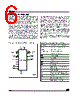
6 / 45 page  M50FW016 6/45 SUMMARY DESCRIPTION The M50FW016 is a 16 Mbit (2Mb x8) non-volatile memory that can be read, erased and reprogrammed. These operations can be performed using a single low voltage (3.0 to 3.6V) supply. For fast programming and fast erasing, an optional 12V power supply can be used to reduce the programming and the erasing times. The memory is divided into blocks that can be erased independently so it is possible to preserve valid data while old data is erased. Blocks can be protected individually to prevent accidental Program or Erase commands from modifying the memory. Program and Erase commands are written to the Command Interface of the memory. An on-chip Program/Erase Controller simplifies the process of programming or erasing the memory by taking care of all of the special operations that are required to update the memory contents. The end of a program or erase operation can be detected and any error conditions identified. The command set required to control the memory is consistent with JEDEC standards. Two different bus interfaces are supported by the memory. The primary interface, the Firmware Hub (or FWH) Interface, uses Intel’s proprietary FWH protocol. This has been designed to remove the need for the ISA bus in current PC Chipsets; the M50FW016 acts as the PC BIOS on the Low Pin Count bus for these PC Chipsets. The secondary interface, the Address/Address Multiplexed (or A/A Mux) Interface, is designed to be compatible with current Flash Programmers for production line programming prior to fitting to a PC Motherboard. The memory is offered in TSOP40 (10 x 20mm) package and it is supplied with all the bits erased (set to ’1’). Figure 2. Logic Diagram (FWH Interface) Table 1. Signal Names (FWH Interface) AI04462 4 FWH4 FWH0- FWH3 VCC M50FW016 CLK VSS 4 IC RP TBL 5 INIT WP ID0-ID3 FGPI0- FGPI4 VPP FWH0-FWH3 Input/Output Communications FWH4 Input Communication Frame ID0-ID3 Identification Inputs FGPI0-FGPI4 General Purpose Inputs IC Interface Configuration RP Interface Reset INIT CPU Reset CLK Clock TBL Top Block Lock WP Write Protect RFU Reserved for Future Use. Leave disconnected. VCC Supply Voltage VPP Optional Supply Voltage for Fast Program and Fast Erase Operations VSS Ground NC Not Connected Internally RFU Reserved for Future Use |
|
Ligação URL |
| ALLDATASHEET é útil para você? [ DONATE ] |
Sobre Alldatasheet | Publicidade | Contato conosco | Privacy Policy | Link para a ficha técnica | roca de Link | Lista de Fabricantes All Rights Reserved©Alldatasheet.com |
| Russian : Alldatasheetru.com | Korean : Alldatasheet.co.kr | Spanish : Alldatasheet.es | French : Alldatasheet.fr | Italian : Alldatasheetit.com Portuguese : Alldatasheetpt.com | Polish : Alldatasheet.pl | Vietnamese : Alldatasheet.vn Indian : Alldatasheet.in | Mexican : Alldatasheet.com.mx | British : Alldatasheet.co.uk | New Zealand : Alldatasheet.co.nz |
|
Family Site : ic2ic.com |
icmetro.com |
 Portuguese ▼
 English
 Chinese
 German
 Japanese
 Russian
 Korean
 Spanish
 French
 Italian
 Portuguese
 Polish
 Vietnamese
 Indian
 Mexican
 British
 New Zealand