|
Os motores de busca de Datasheet de Componentes eletrônicos |
|
|
Os motores de busca de Datasheet de Componentes eletrônicos |
|
AD8132ARZ-R7 Folha de dados(PDF) 23 Page - Analog Devices |
|
|
|||||||||||||||||||||||||||||
AD8132ARZ-R7 Folha de dados(HTML) 23 Page - Analog Devices |
|
|
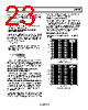
23 / 32 page  AD8132 Rev. F | Page 23 of 32 When using the AD8132 in gain configurations where β1 ≠ β2, differential output noise appears due to input-referred voltage noise in the VOCM circuitry according to the following formula: ⎥ ⎥ ⎦ ⎤ ⎢ ⎢ ⎣ ⎡ + − = β2 β1 β2 β1 V V NOCM OND 2 where VOND is the output differential noise and VNOCM is the input-referred voltage noise on VOCM. CALCULATING INPUT IMPEDANCE OF THE APPLICATION CIRCUIT The effective input impedance of a circuit, such as that in Figure 64, at +DIN and −DIN, depends on whether the amplifier is being driven by a single-ended or differential signal source. For balanced differ- ential input signals, the input impedance (RIN, dm) between the inputs (+DIN and −DIN) is simply G dm IN, R R × = 2 In the case of a single-ended input signal (for example, if −DIN is grounded and the input signal is applied to +DIN), the input impedance becomes ()⎟ ⎟ ⎟ ⎟ ⎠ ⎞ ⎜ ⎜ ⎜ ⎜ ⎝ ⎛ + × − = F G F G dm IN, R R R R R 2 1 The circuit input impedance is effectively higher than it would be for a conventional op amp connected as an inverter because a fraction of the differential output voltage appears at the inputs as a common-mode signal, partially bootstrapping the voltage across the Input Resistor RG. INPUT COMMON-MODE VOLTAGE RANGE IN SINGLE-SUPPLY APPLICATIONS The AD8132 is optimized for level-shifting ground-referenced input signals. For a single-ended input, this implies that the voltage at −DIN in Figure 64 is 0 V when the amplifier’s negative power supply voltage (at V−) was also set to 0 V. SETTING THE OUTPUT COMMON-MODE VOLTAGE The AD8132s VOCM pin is internally biased at a voltage approx- imately equal to the midsupply point (average value of the voltage on V+ and V−). Relying on this internal bias results in an output common-mode voltage that is within approximately 100 mV of the expected value. In cases where more accurate control of the output common-mode level is required, it is best practice that an external source or resistor divider (with RSOURCE < 10 kΩ) be used. The output common-mode offset values in the Specifications section assume the VOCM input is driven by a low impedance voltage source. DRIVING A CAPACITIVE LOAD A purely capacitive load can react with the pin and bond wire inductance of the AD8132, resulting in high frequency ringing in the pulse response. One way to minimize this effect is to place a small capacitor across each of the feedback resistors. The added capacitance must be small to avoid destabilizing the amplifier. An alternative technique is to place a small resistor in series with the amplifier outputs, as shown in Figure 60. OPEN-LOOP GAIN AND PHASE Open-loop gain and phase plots are shown in Figure 65 and Figure 66. –20 –10 0 10 20 30 40 50 60 0.1 1 10 100 1000 FREQUENCY (MHz) RL, dm = 2kΩ Figure 65. Open-Loop Gain Plot –200 –180 –160 –140 –120 –100 –80 –60 –40 –20 0 20 40 0.1 1 10 100 1000 FREQUENCY (MHz) RL, dm = 2kΩ Figure 66. Open-Loop Phase Plot |
|
Ligação URL |
| ALLDATASHEET é útil para você? [ DONATE ] |
Sobre Alldatasheet | Publicidade | Contato conosco | Privacy Policy | Link para a ficha técnica | roca de Link | Lista de Fabricantes All Rights Reserved©Alldatasheet.com |
| Russian : Alldatasheetru.com | Korean : Alldatasheet.co.kr | Spanish : Alldatasheet.es | French : Alldatasheet.fr | Italian : Alldatasheetit.com Portuguese : Alldatasheetpt.com | Polish : Alldatasheet.pl | Vietnamese : Alldatasheet.vn Indian : Alldatasheet.in | Mexican : Alldatasheet.com.mx | British : Alldatasheet.co.uk | New Zealand : Alldatasheet.co.nz |
|
Family Site : ic2ic.com |
icmetro.com |
 Portuguese ▼
 English
 Chinese
 German
 Japanese
 Russian
 Korean
 Spanish
 French
 Italian
 Portuguese
 Polish
 Vietnamese
 Indian
 Mexican
 British
 New Zealand