|
Os motores de busca de Datasheet de Componentes eletrônicos |
|
|
Os motores de busca de Datasheet de Componentes eletrônicos |
|
ADP3193 Folha de dados(PDF) 7 Page - Analog Devices |
|
|
|||||||||||||||||||||||||||||
ADP3193 Folha de dados(HTML) 7 Page - Analog Devices |
|
|
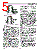
7 / 16 page  REV. A ADP3158/ADP3178 –7– CT Selection for Operating Frequency The ADP3158 and ADP3178 use a constant off-time architecture with tOFF determined by an external timing capacitor CT. Each time the high-side N-channel MOSFET switch turns on, the volt- age across CT is reset to 0 V. During the off-time, CT is charged by a constant current of 150 µA. Once CT reaches 3.0 V, a new on-time cycle is initiated. The value of the off-time is calculated using the continuous-mode operating frequency. Assuming a nominal operating frequency (fNOM) of 200 kHz at an output volt- age of 1.7 V, the corresponding off-time is: t V Vf t V V kHz s OFF OUT IN NOM OFF = × =− ×= 1 1 1 17 5 1 200 33 – . . µ (1) The timing capacitor can be calculated from the equation: C tI V sA V pF T OFF CT TTH = × = µ× µ ≈ () . 3 3 150 3 150 (2) (3) f t VI R R R V VI R R R R MIN OFF IN O MAX DS ON HSF SENSE L OUT IN O MAX DS ON HSF SENSE L DS ON LSF =× ×+ + ×+ + 1 – () – – ( – ) () ( ) ( ) () () ) The converter only operates at the nominal operating frequency at the above-specified VOUT and at light load. At higher values of VOUT, or under heavy load, the operating frequency decreases due to the parasitic voltage drops across the power devices. The actual minimum frequency at VOUT = 1.7 V is calculated to be 195 kHz (see Equation 3), where: RDS(ON)HSF is the resistance of the high-side MOSFET (estimated value: 14 m Ω) RDS(ON)LSF is the resistance of the low-side MOSFET (estimated value: 6 m Ω) RSENSE is the resistance of the sense resistor (estimated value: 4 m Ω) RL is the resistance of the inductor (estimated value: 3 m Ω) Inductance Selection The choice of inductance determines the ripple current in the inductor. Less inductance leads to more ripple current, which increases the output ripple voltage and the conduction losses in the MOSFETs, but allows using smaller-size inductors and, for a specified peak-to-peak transient deviation, output capacitors with less total capacitance. Conversely, a higher inductance means lower ripple current and reduced conduction losses, but requires larger-size inductors and more output capacitance for the same peak-to-peak transient deviation. The following equation shows the relationship between the inductance, oscillator frequency, peak-to-peak ripple current in an inductor and input and output voltages. L Vt I OUT OFF L RIPPLE = × () (4) For 4 A peak-to-peak ripple current, which corresponds to approximately 25% of the 15 A full-load dc current in an inductor, Equation 4 yields an inductance of L Vs A H = ×µ =µ 17 33 4 14 .. . A 1.5 µH inductor can be used, which gives a calculated ripple current of 3.8 A at no load. The inductor should not saturate at the peak current of 17 A and should be able to handle the sum of the power dissipation caused by the average current of 15 A in the winding and the core loss. Designing an Inductor Once the inductance is known, the next step is either to design an inductor or find a standard inductor that comes as close as possible to meeting the overall design goals. The first decision in designing the inductor is to choose the core material. There are several possibilities for providing low core loss at high frequen- cies. Two examples are the powder cores (e.g., Kool-M µ® from Magnetics, Inc.) and the gapped soft ferrite cores (e.g., 3F3 or 3F4 from Philips). Low frequency powdered iron cores should be avoided due to their high core loss, especially when the inductor value is relatively low and the ripple current is high. Two main core types can be used in this application. Open magnetic loop types, such as beads, beads on leads, and rods and slugs, provide lower cost but do not have a focused mag- netic field in the core. The radiated EMI from the distributed magnetic field may create problems with noise interference in the circuitry surrounding the inductor. Closed-loop types, such as pot cores, PQ, U, and E cores, or toroids, cost more, but have much better EMI/RFI performance. A good compromise between price and performance are cores with a toroidal shape. |
|
|
Ligação URL |
| ALLDATASHEET é útil para você? [ DONATE ] |
Sobre Alldatasheet | Publicidade | Contato conosco | Privacy Policy | Link para a ficha técnica | roca de Link | Lista de Fabricantes All Rights Reserved©Alldatasheet.com |
| Russian : Alldatasheetru.com | Korean : Alldatasheet.co.kr | Spanish : Alldatasheet.es | French : Alldatasheet.fr | Italian : Alldatasheetit.com Portuguese : Alldatasheetpt.com | Polish : Alldatasheet.pl | Vietnamese : Alldatasheet.vn Indian : Alldatasheet.in | Mexican : Alldatasheet.com.mx | British : Alldatasheet.co.uk | New Zealand : Alldatasheet.co.nz |
|
Family Site : ic2ic.com |
icmetro.com |
 Portuguese ▼
 English
 Chinese
 German
 Japanese
 Russian
 Korean
 Spanish
 French
 Italian
 Portuguese
 Polish
 Vietnamese
 Indian
 Mexican
 British
 New Zealand