|
Os motores de busca de Datasheet de Componentes eletrônicos |
|
|
Os motores de busca de Datasheet de Componentes eletrônicos |
|
LMV393DMR2G Folha de dados(PDF) 12 Page - ON Semiconductor |
|
|
|||||||||||||||||||||||||||||
LMV393DMR2G Folha de dados(HTML) 12 Page - ON Semiconductor |
|
|
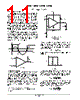
12 / 19 page  LMV331, NCV331, LMV393, LMV339 http://onsemi.com 12 VO HIGH +VCC R3 VT1 R1 R2 Figure 22. VO LOW +VCC R3 VT2 R1 R2 Figure 23. Non−inverting Configuration with Hysteresis A non−inverting comparator is shown in Figure 24. Figure 24. +VCC VREF + − R2 VIN R1 VA RPULL−UP VO RLOAD The hysteresis band (Figure 25) of the non−inverting configuration is defined as follows: DV in + VCCR1 R2 VIN1 VIN2 VIN VO VCC 0 Figure 25. When VIN is much less than the voltage at the inverting input (VREF), then the output is low. R2 can then be viewed as being connected to ground (Figure 26). To calculate the voltage required at VIN to trip the comparator high, the following equation is used: V in1 + V ref (R1 ) R2) R 2 When the output is high, VIN must less than or equal to VREF (VIN ≤ VREF) before the output will be low again (Figure 27). The following equation is used to calculate the voltage at VIN to switch the output back to the low state: V in2 + V ref (R1 ) R2) * VCCR1 R 2 R2 R1 VA = VREF VIN2 VO HIGH +VCC Figure 26. R1 R2 VA = VREF VO LOW VIN1 Figure 27. Termination of Unused Inputs Proper termination of unused inputs is a good practice to keep the output from ‘chattering.’ For example, if one channel of a dual or quad package is not being used, then the inputs must be connected to a defined state. The recommended connections would be to tie one input to VCC and the other input to ground. |
|
|
Ligação URL |
| ALLDATASHEET é útil para você? [ DONATE ] |
Sobre Alldatasheet | Publicidade | Contato conosco | Privacy Policy | Link para a ficha técnica | roca de Link | Lista de Fabricantes All Rights Reserved©Alldatasheet.com |
| Russian : Alldatasheetru.com | Korean : Alldatasheet.co.kr | Spanish : Alldatasheet.es | French : Alldatasheet.fr | Italian : Alldatasheetit.com Portuguese : Alldatasheetpt.com | Polish : Alldatasheet.pl | Vietnamese : Alldatasheet.vn Indian : Alldatasheet.in | Mexican : Alldatasheet.com.mx | British : Alldatasheet.co.uk | New Zealand : Alldatasheet.co.nz |
|
Family Site : ic2ic.com |
icmetro.com |
 Portuguese ▼
 English
 Chinese
 German
 Japanese
 Russian
 Korean
 Spanish
 French
 Italian
 Portuguese
 Polish
 Vietnamese
 Indian
 Mexican
 British
 New Zealand