8-419
RF2890
Rev A4 040421
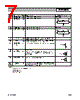
IF Output Interface Network
Single-End IF Matching
L1, C1, C2, and R form a current combiner which performs a differential to single-ended conversion at the IF frequency
and sets the output impedance. In most cases, the resonance frequency is independent of R and can be set according to
the following equation:
Where CEQ is the equivalent stray capacitance and capacitance looking into pins 9 and 10. An average value to use for
CEQ is 2.5pF.
R can then be used to set the output impedance according to the following equation:
where ROUT is the desired output impedance and RP is the parasitic equivalent parallel resistance of L1.
C2 should first be set to 0 and C1 should be chosen as high as possible (not greater than 39pF), while maintaining an RP
of L1 that allows for the desired ROUT. If the self-resonant frequencies of the selected C1 produce unsatisfactory linearity
performance, their values may be reduced and compensated for by including C2 capacitor with a value chosen to main-
tain the desired FIF frequency.
L2 and C3 serve dual purposes. L2 serves as an output bias choke, and C3 serves as a series DC block.
In addition, L2 and C3 may be chosen to form an impedance matching network if the input impedance of the IF filter is
not equal to ROUT. Otherwise, L2 is chosen to be large (suggested 120nH) and C3 is chosen to be large (suggested
22nF) if a DC path to ground is present in the IF filter, or omitted if the filter is DC-blocked.
IF-
IF+
C2
R
L1
L2
V
CC
100 pF
C3
IF Saw
4
5
9
10
IF+
IF-
C1
C1
fIF
1
L1
2
------ C
1
2C2 CEQ
++
()
2
π
-----------------------------------------------------------
=
R
1
4 ROUT
⋅
---------------------
1
RP
------
–
1
–
=


 Portuguese ▼
 English
 Chinese
 German
 Japanese
 Russian
 Korean
 Spanish
 French
 Italian
 Portuguese
 Polish
 Vietnamese
 Indian
 Mexican
 British
 New Zealand