7 / 14 page
8-415
RF2890
Rev A4 040421
Pin
Function
Type Description
Interface Schematic
15
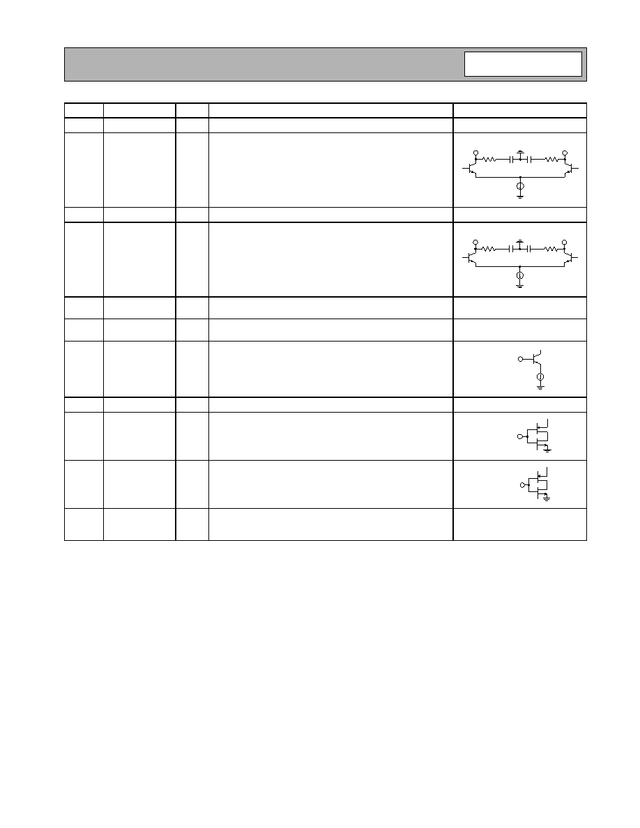
CDMA IF-
AO
CDMA IF output. Open collector.
See pin 16.
16
CDMA IF+
AO
CDMA IF output. Open collector.
17
GPS IF-
AO
GPS IF output. Open collector.
See pin 18.
18
GPS IF+
AO
GPS IF output. Open collector.
19
ISET2
AO
Resistor to ground sets mixer currents in both bands. Higher
resistance results in lower currents.
20
ISET1
AO
Resistor to ground sets the LNA current in boost mode (both
LNAs). Higher resistance results in lower current.
21
CELL MIX
IN
AI
Cellular mixer RF single-end input. Externally matched to 50
Ω.
22
NC
No connection.
23
DIV SEL
DI
Logic input. Logic low enables LO divide-by-2 in cellular
mode, DIV SEL must be set high in GPS mode. See VCO
options table.
24
ENABLE
DI
Logic input. Low level powers down the IC.
Pkg
Base
GND
P
Ground connection. The backside of the package should be
soldered to a top side ground pad which is connected to the
ground plane with multiple vias.
Legend:
DI=Digital Input from Baseband Chip
AI=Analog Input
AO=Analog Output
P=VCC or GND
CDMA IF+
CDMA IF-
GPS IF+
GPS IF-
CELL MIX IN
DIV SEL
ENABLE

 Portuguese ▼
 English
 Chinese
 German
 Japanese
 Russian
 Korean
 Spanish
 French
 Italian
 Portuguese
 Polish
 Vietnamese
 Indian
 Mexican
 British
 New Zealand