|
Os motores de busca de Datasheet de Componentes eletrônicos |
|
|
Os motores de busca de Datasheet de Componentes eletrônicos |
|
11C90DC Folha de dados(PDF) 1 Page - National Semiconductor (TI) |
|
|
|
|||||||||||||||||||||||||||||
11C90DC Folha de dados(HTML) 1 Page - National Semiconductor (TI) |
|
|
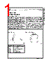
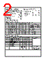
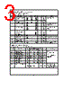
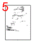
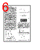
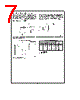
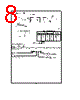
1 / 10 page  TLF9892 Not Intended For New Designs August 1992 11C9011C91 650 MHz Prescalers General Description The 11C90 and 11C91 are high-speed prescalers designed specifically for communication and instrumentation applica- tions All discussions and examples in this data sheet are applicable to the 11C91 as well as the 11C90 The 11C90 will divide by 10 or 11 and the 11C91 by 5 or 6 both over a frequency range from DC to typically 650 MHz The division ratio is controlled by the Mode Control The divide-by-10 or -11 capability allows the use of pulse swal- lowing techniques to control high-speed counting modulos by lower-speed circuits The 11C90 may be used with either ECL or TTL power supplies In addition to the ECL outputs Q and Q the 11C90 contains an ECL-to-TTL converter and a TTL output The TTL output operates from the same VCC and VEE levels as the counter but a separate pin is used for the TTL circuit VEE This mini- mizes noise coupling when the TTL output switches and also allows power consumption to be reduced by leaving the separate VEE pin open if the TTL output is not used To facilitate capacitive coupling of the clock signal a 400X resistor (VREF) is connected internally to the VBB reference Connecting this resistor to the Clock Pulse input (CP) auto- matically centers the input about the switching threshold Maximum frequency operation is achieved with a 50% duty cycle Each of the Mode Control inputs is connected to an internal 2kX resistor with the other end uncommitted (RM1 and RM2) An M input can be driven from a TTL circuit operating from the same VCC by connecting the free end of the asso- ciated 2 kX resistor to VCCA When an M input is driven from the ECL circuit the 2 kX resistor can be left open or if required can be connected to VEE to act as a pull-down resistor Logic Symbol TLF9892 – 2 Pin Names Description CE Count Enable Input (Active LOW) CP Clock Pulse Input Mn Count Modulus Control Input MS Asynchronous Master Set Input Q Q ECL Outputs QTTL TTL Output RMn 2kX Resistor to Mn VREF 400X Resistor to VBB Connection Diagram 16-Pin DIP TLF9892 – 1 C1995 National Semiconductor Corporation RRD-B30M115Printed in U S A |
Nº de peça semelhante - 11C90DC |
|
Descrição semelhante - 11C90DC |
|
|
|
Ligação URL |
| ALLDATASHEET é útil para você? [ DONATE ] |
Sobre Alldatasheet | Publicidade | Contato conosco | Privacy Policy | Link para a ficha técnica | roca de Link | Lista de Fabricantes All Rights Reserved©Alldatasheet.com |
| Russian : Alldatasheetru.com | Korean : Alldatasheet.co.kr | Spanish : Alldatasheet.es | French : Alldatasheet.fr | Italian : Alldatasheetit.com Portuguese : Alldatasheetpt.com | Polish : Alldatasheet.pl | Vietnamese : Alldatasheet.vn Indian : Alldatasheet.in | Mexican : Alldatasheet.com.mx | British : Alldatasheet.co.uk | New Zealand : Alldatasheet.co.nz |
|
Family Site : ic2ic.com |
icmetro.com |
 Portuguese ▼
 English
 Chinese
 German
 Japanese
 Russian
 Korean
 Spanish
 French
 Italian
 Portuguese
 Polish
 Vietnamese
 Indian
 Mexican
 British
 New Zealand