|
Os motores de busca de Datasheet de Componentes eletrônicos |
|
|
Os motores de busca de Datasheet de Componentes eletrônicos |
|
MP4603 Folha de dados(PDF) 8 Page - Monolithic Power Systems |
|
|
|||||||||||||||||||||||||||||
MP4603 Folha de dados(HTML) 8 Page - Monolithic Power Systems |
|
|
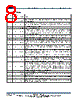
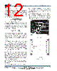
8 / 18 page  MP4603 – WHITE LED DRIVER FOR LARGE LCD TV BACKLIGHTS MP4603 Rev. 1.0 www.MonolithicPower.com 8 4/27/2012 MPS Proprietary Information. Patent Protected. Unauthorized Photocopy and Duplication Prohibited. © 2012 MPS. All Rights Reserved.MP4603 PIN FUNCTIONS Pin # SOIC16 Pin # TSSOP 16-EP Name Description 2 1 VIN Positive Voltage Input. Requires a decoupling capacitor to prevent large input- voltage spikes. 1 2 FAULT Fault Condition Output. Open drain with reference to INGND. FAULT is high-Z during normal operation, and pulled to INGND when LED short protection or LED open protection trigger. 3 3 INGND Input Ground Reference. 4 4 SYN Frequency Synchronization Input. The switching frequency can be synchronized with an external clock. Multiple ICs’ frequencies can also be synchronized without the external clock by connecting all the SYN pins together. They follow the highest set frequency. 5 5 PWM PWM Dimming Input. Apply a 100Hz to 50kHz square wave signal with amplitude greater than 2.2V. The PWM pin voltage is high if left floating. 6 6 EN Enable Input Pin. A voltage greater than 1.5V will turn on the chip. 7 7 ADIM Analog Dimming Input. A voltage in range of 0V to 1.2V on ADIM pin adjusts the LED current from 0 to 100%. The ADIM pin voltage is high (about 3.3V) if left floating. 8 8 FST Frequency Set. A resistor from FST to VSS sets the switching frequency if there is no SYN input. If left open, switching frequency reverts to an internal default value. 9 9 SLOPE Programmable Slope Compensation. Connect a resistor from SLOPE to VSS to set the slope-compensation peak amplitude. If left open, slope compensation reverts to an internal default value. 10 10 COMP Error Amplifier Output. Connect a capacitor ≥1nF from the COMP pin to VSS to improve the stability and to provide a soft-start on start-up or for PWM dimming. 11 11 FB LED Current Feedback. The MP4603 regulates the voltage across the current sensing resistor between FB and VSS with 200mV. If the FB voltage exceeds 300mV for 450µs or exceeds 600mV, LED short protection triggers. 12 12 OVP Over Voltage Protection. Use one external resistor voltage divider from the output to VSS to program the OVP threshold. This voltage references VSS. When the OVP pin voltage reaches the 1.2V threshold, the switch turns off and the IC latches off. When the OVP pin voltage falls below 0.4V and the FB pin voltage is less than 0.1V, the chip frequency folds back. Program the OVP pin voltage from 0.4V to 1.2V for normal operation. 13 13 DGD LED Dimming-Switch Gate Drive Output. 14 14 VSS Negative Voltage Output. The voltage reference for OVP, FB, COMP, SLOPE, DGD and FST. 15 15 SW Switch Output. The source of the internal MOSFET switch. Connect to the power inductor and cathode of the Schottky rectifier. 16 16 BST Bootstrap. Connect a capacitor between the SW and BST pins to form a floating supply across the power switch driver. |
|
|
Ligação URL |
| ALLDATASHEET é útil para você? [ DONATE ] |
Sobre Alldatasheet | Publicidade | Contato conosco | Privacy Policy | Link para a ficha técnica | roca de Link | Lista de Fabricantes All Rights Reserved©Alldatasheet.com |
| Russian : Alldatasheetru.com | Korean : Alldatasheet.co.kr | Spanish : Alldatasheet.es | French : Alldatasheet.fr | Italian : Alldatasheetit.com Portuguese : Alldatasheetpt.com | Polish : Alldatasheet.pl | Vietnamese : Alldatasheet.vn Indian : Alldatasheet.in | Mexican : Alldatasheet.com.mx | British : Alldatasheet.co.uk | New Zealand : Alldatasheet.co.nz |
|
Family Site : ic2ic.com |
icmetro.com |
 Portuguese ▼
 English
 Chinese
 German
 Japanese
 Russian
 Korean
 Spanish
 French
 Italian
 Portuguese
 Polish
 Vietnamese
 Indian
 Mexican
 British
 New Zealand